Operating Instructions ACTIVE 06/07188
188 Operating Instructions ACTIVE 06/07
Multiple motor operation
Parameter
Operation Mode 571 = 1 or 11
In multiple motor operation, it is assumed that for each data set a corresponding mo-
tor is used. For this, one motor and one motor protection switch are assigned to each
data set. In this operation mode, the rated values of the active data set are moni-
tored. The current output current of the frequency inverter is only taken into account
if the motor protection switch is activated by the data set. In the motor protection
switch of the other data sets, zero current is expected, with the result that the ther-
mal decay functions are taken into account. In combination with the data set change-
over, the function of the motor protection switches is similar to that of motors con-
nected alternately to the mains with their own protection switches.
Single motor operation
Parameter
Operation Mode 571 = 2 or 22
In single motor operation, only one motor protection witch, which monitors the output
current of the frequency inverter, is active. In the case of a data set change-over,
only the switch-off limits derived from the rated machine parameters are changed
over. Accumulated thermal values are used after the change-over as well. In the case
of the data set change-over, please ensure that the machine data are stated identi-
cally for all data sets. In combination with the data set change-over, the function of
the motor protection switch is similar to that of motors connected alternately to the
mains with one common protection switch.
Motor protection, in particular self-ventilation motors, is improved via the
Frequency
Limit
572 which can be set as a percentage of the rated frequency. The measured
output current in operating points below the frequency limit is assessed by a factor of
2 higher in the calculation of the trigger characteristic.
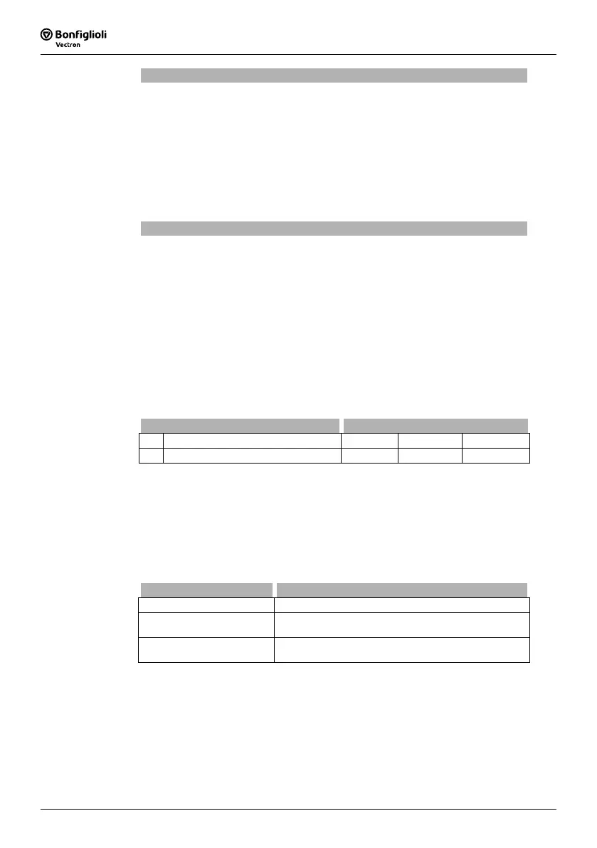
Parameter Settings
No. Description Min. Max. Fact. sett.
572 Frequency Limit 0 % 300 % 0 %
17.6 V-belt Monitoring
Continuous monitoring of the load behavior and thus of the connection between the
3-phase machine and the load is the task of the V-belt monitoring system. The pa-
rameter
Operation Mode 581 defines the function behavior if the Active Current 214
(sensor-less control) or the torque-forming current component
Isq 216 (field-oriented
control method) is below the set
Trigger Limit Iactive 582 for longer than the pa-
rameterized
Delay Time 583.
Operation mode 581 Function
0 - Off The function is deactivated.
1 - Warning
If the active current drops below the threshold value,
the warning "A8000" is displayed.
2 - Error
The unloaded drive is switched off and fault message
"F0402" is displayed.
 Loading...


