Operating Instructions ACTIVE06/07 173
06/07 Operating Instructions ACTIVE 173
The guided commissioning has selected the parameters of the current controller in
such a way that they can be used without having to be changed in most applications.
If, in exceptional cases, an optimization of the behavior of the current controllers is to
be done, the reference value step-change during the flux-formation phase can be
used for this. If parameterized appropriately, the reference value of the flux-forming
current components jumps to the value
Current During Flux-Formation 781 and
then changes in a controlled way to the magnetizing current after the expiry of the
Maximum Flux-Formation Time 780. The operating point necessary for the adjust-
ment demands the setting of parameter
Minimum Frequency 418 to 0.00 Hz, as the
drive is accelerated after magnetizing. The measurement of the step response, which
is defined by the ratio of the currents mentioned, should be done in the motor supply
line by means of a measuring current transformer of a sufficient bandwidth.
Note: The internally calculated actual value for the flux-forming current compo-
nent cannot be output via the analog output for this measurement as the
time resolution of the measurement is not sufficient.
To set the parameters of the PI controller, the
Amplification 700 is increased first
until the actual value overshoots distinctly during the control process. Now, the ampli-
fication is reduced to about a half again and then the
Integral Time 701 is synchro-
nized until actual value overshoots slightly during the control process.
The settings of the current controllers should not be too dynamic in order to ensure a
sufficient reserve range. The control tends to increased oscillations if the reserve
range is reduced.
The dimensioning of the current controller parameters by calculation of the time con-
stant is to be done for a switching frequency of 2 kHz. For other switching frequen-
cies, the values are adapted internally so that the setting can remain unchanged for
all switching frequencies. The dynamic properties of the current controller improve if
the switching and scanning frequency increases.
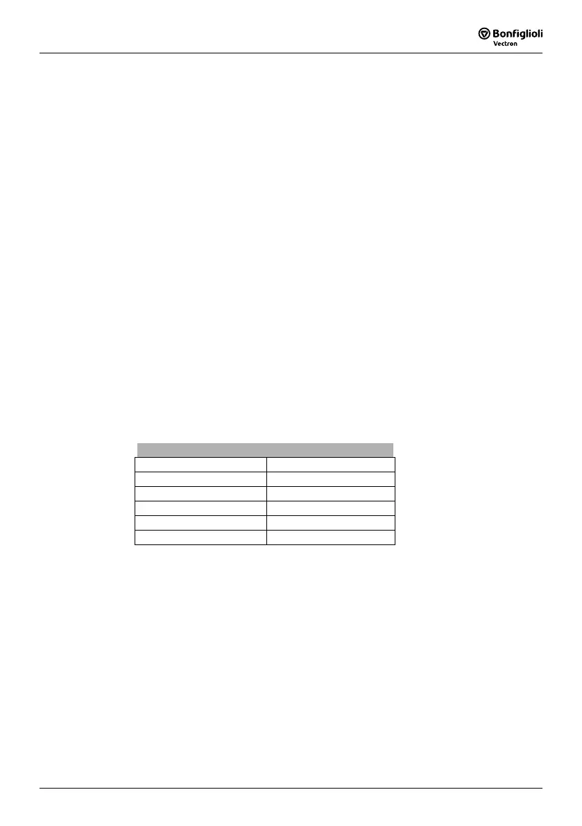
The fixed time interval for the modulation results in the following scanning frequencies
of the current controller via parameter
Switching Frequency 400.
Settings
Switching frequency Scanning Frequency
2 kHz
1)
2 kHz
4 kHz 4 kHz
8 kHz 8 kHz
12 kHz 8 kHz
16 kHz 8 kHz
1)
This switching frequency can only be set for the parameter Min. Switching Fre-
quency
401.
 Loading...


