TRANSMISSION
KUKJE MACHINERY CO., LTD.
90
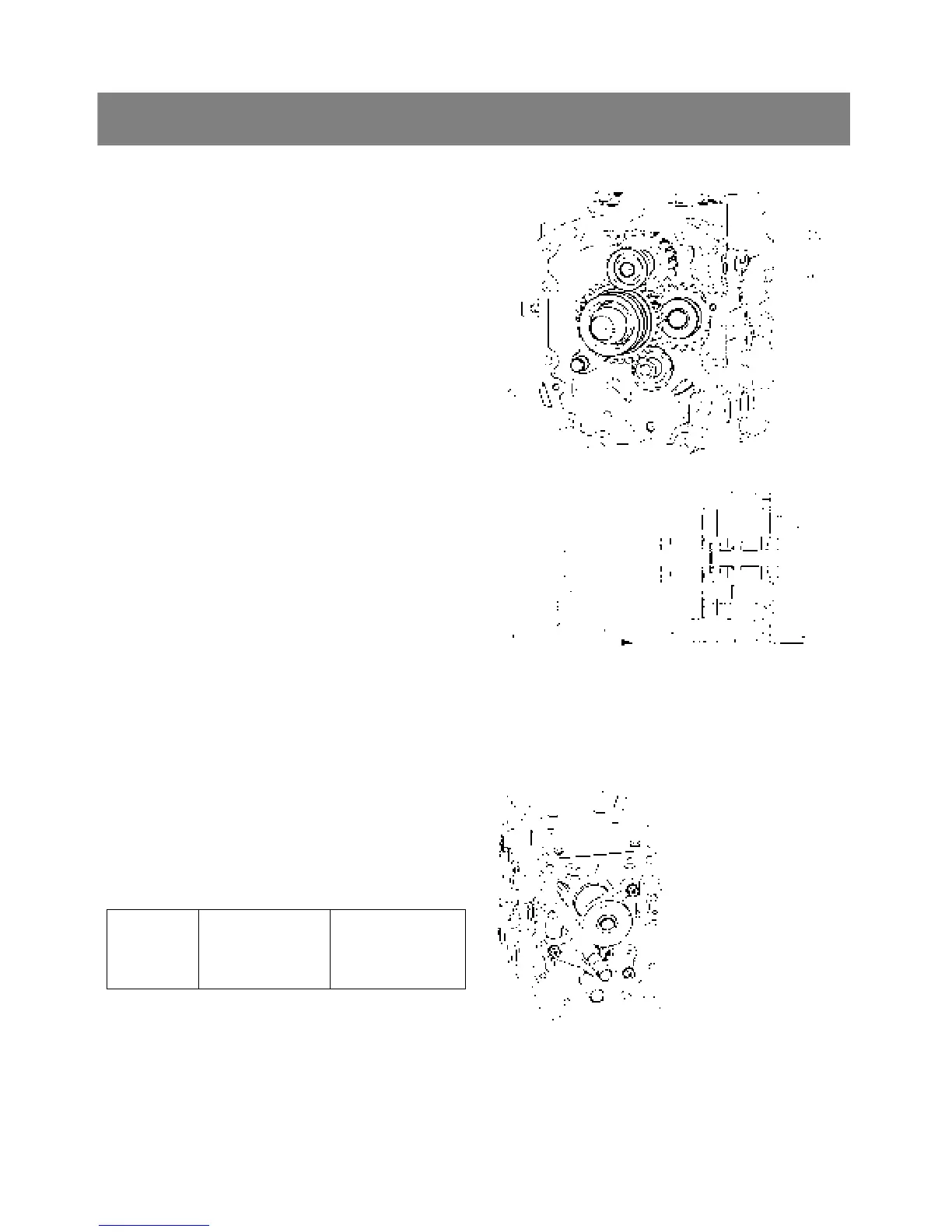
5. CHECKING, DISASSEMBLING AND SERVICING
< 4
th
Gear shaft and spiral bevel pinion shaft >
1. Remove the spiral bevel pinion shaft(3) with 15T-
29T shifter gear(2), 13T gear(8) and shift fork(4).
2. Remove the 4
th
gear shaft(1) with 18T gear.
▷ Reassembling
9 When installing the spiral bevel pinion shaft, be
sure to install the shims(7).
9 Install the shift fork(4), so that the fork rod(9) of
the shift rod(5) faces rearward.
◈ Important
¾ When disassembling the spiral bevel pinion
shaft(3), be sure to replace the external snap
ring(6) with new one.
*. PART NAME
1) Gear shaft 2) Shifter gear
3) Spiral bevel pinion shaft 4) Shift fork
5) Shift fork rod 6) External snap ring
7) Shim 8) 13T gear
9) Fork rod
A) Rear
< Bearing holder >
1. Remove the external snap ring and remove the
27T gear(1).
2. Remove the bearing holder mounting screws and
remove the bearing holder(2).
▷ Reassembling
Tightening
torque
Bearing holder
mounting screw
50 to 55 Nm
5.1 to 5.6 kgfm
36.9 to 40.1 ft-lbs
*. PART NAME
1) 27T Gear
2) Bearing holder
(5)
(4)
(9)
(3) (6)
(7)
(8) (2)
(2)
(1)