TRANSMISSION
KUKJE MACHINERY CO., LTD.
93
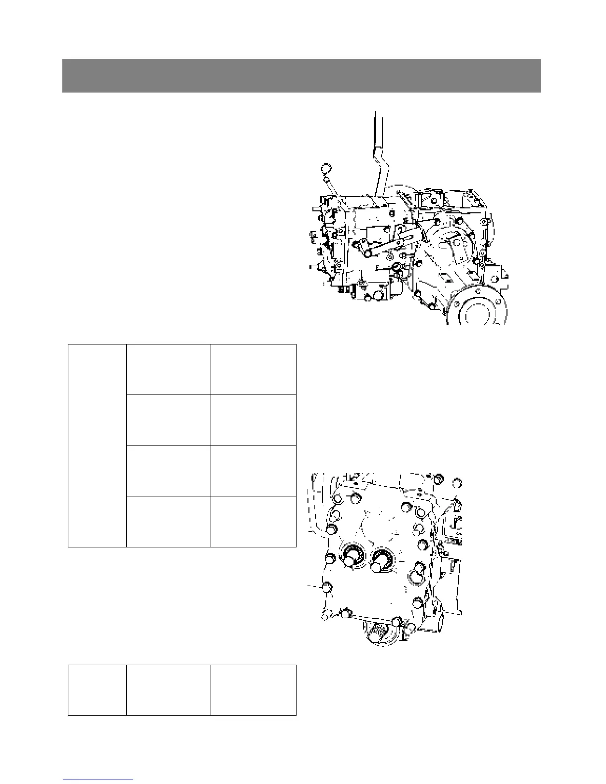
5. CHECKING, DISASSEMBLING AND SERVICING
*. PART NAME
1) Mid-PTO case 2) Transmission case
3) Front wheel drive lever 4) Differential case
5) Rear axle case 6) Drawbar frame
< Separating rear axle case, mid-PTO case,
drawbar frame and transmission case >
1. Remove the front wheel drive lever(3).
2. Remove the rear axle cases(5) from differential
case.
3. Remove the mid-PTO case(1) from transmission
case.
4. Remove the drawbar frame(6).
5. Separate the transmission case(2) and differential
case(4).
▷ Reassembling
9 Apply gasket to the face of the rear axle cases,
mid-PTO case and transmission case to
differential case.
Drawbar frame
mounting screw
77.5 to 90.2 Nm
7.9 to 9.2 kgfm
57.1 to 66.5 ft-lbs
Mid-PTO case
mounting screw
48.1 to 55.9 Nm
4.9 to 5.7 kgfm
35.4 to 41.2 ft-lbs
Transmission case
mounting screw
and nut
48.1 to 55.9 Nm
4.9 to 5.7 kgfm
35.4 to 41.2 ft-lbs
Tightening
torque
Rear axle case
mounting screw
48.1 to 55.9 Nm
4.9 to 5.7 kgfm
35.4 to 41.2 ft-lbs
< Front cover >
1. Remove the front cover mounting screw and
remove the front cover(1).
▷ Reassembling
9 Apply liquid gasket to joint face of the front
cover to transmission case.
Tightening
torque
Front case
mounting screw
48.1 to 55.9 Nm
4.9 to 5.7 kgfm
35.4 to 41.2 ft-lbs
*. PART NAME
1) Front cover