138 Brocade MLX Series and NetIron XMR Hardware Installation Guide
53-1003821-01
Installing 2x100GbE interface modules in NetIron XMR routers
3
1. Upgrade the software on all management modules and interface modules to Multi-Service
IronWare R05.6.00 or later. For specific upgrade instructions, refer to the Multi-Service
IronWare Upgrade Guide.
2. Before you install your 2x100G interface module into a working device, you must change the
system tm-credit-size to 1024b (which readies the device to forward 100 Gbps traffic). Log into
your system and enter the following commands in the configuration level of the CLI. Remember
to write to memory and reload the device.
Brocade# config
Brocade(config)# system-init tm-credit-size credit_1024b
Brocade(config)# exit
Brocade# write memory
Brocade# reload
The system-init tm-credit-size command is only available in R05.2.00 or later, so it is important
to upgrade all software to R05.6.00 before you install your 2x100G module.
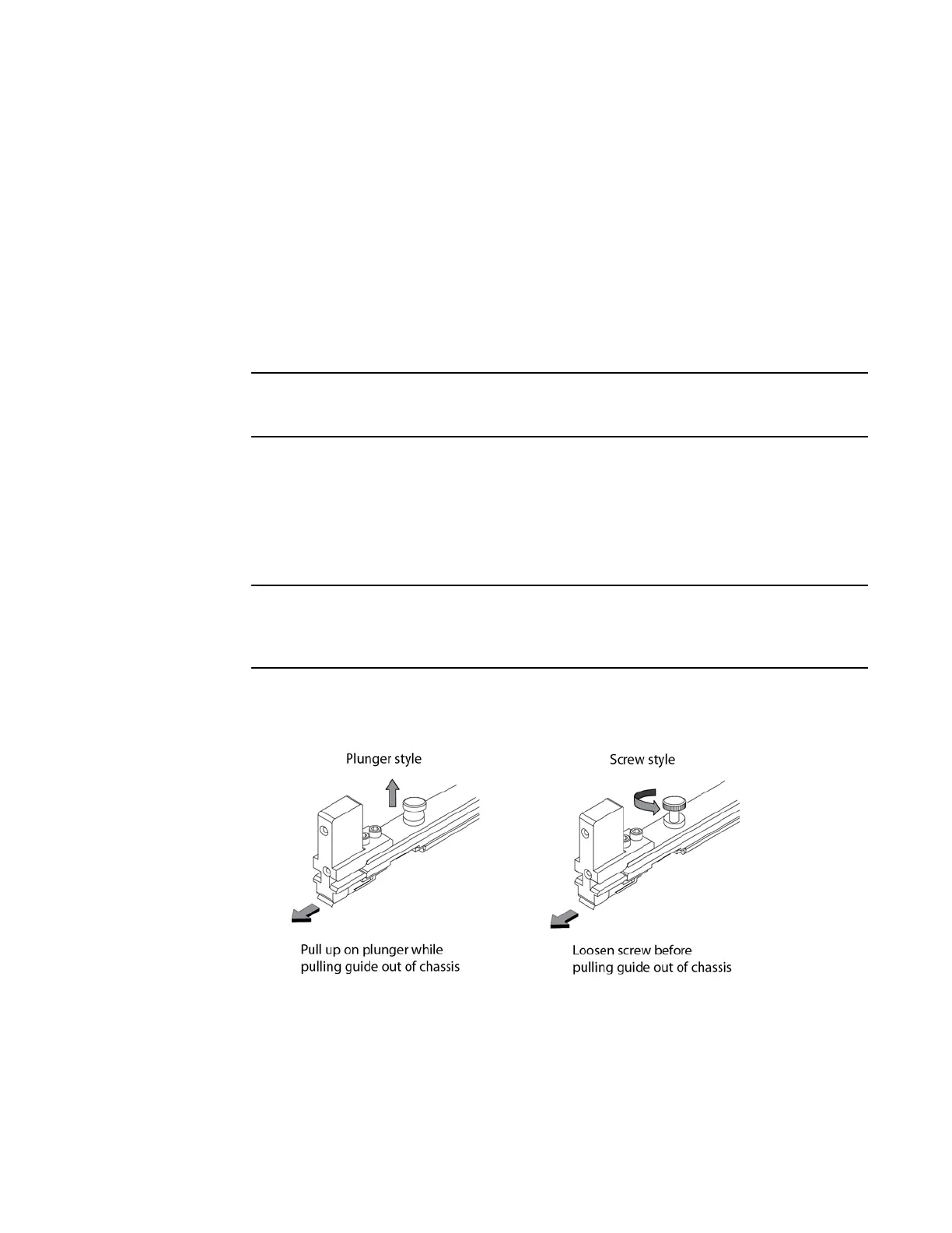
3. Remove the center slot guide. In some devices, you must lift a plunger to remove the center
slot guide. Be sure to keep the plunger raised so that it does not reseat while you are removing
the guide. In some devices, you must loosen a screw to remove the center slot guide. Figure 89
shows the two types of center slot guides.
Remove the guide carefully so that it does not move from side to side. Excess movement of the
guide may damage pins on the backplane before it is fully removed from the chassis.
Do not discard the center slot guide, as you will need it if you want to revert to a 2-slot
configuration. If you misplace your center slot guide, you can purchase a replacement from
Brocade.
FIGURE 89 Removing the center slot guide
4. Remove the two connector covers from the rear connectors of the module. Refer to Figure 90.
5. Remove the port cover from one or both ports, depending on how you plan to use your module.
If you are using one port only (always Port 1), you must leave the port cover in the inactive port
(always Port 2). Port covers are designed for a tight fit and will take some effort to remove.
Refer to Figure 90.
 Loading...
