Brocade MLX Series and NetIron XMR Hardware Installation Guide 139
53-1003821-01
Installing 2x100GbE interface modules in NetIron XMR routers
3
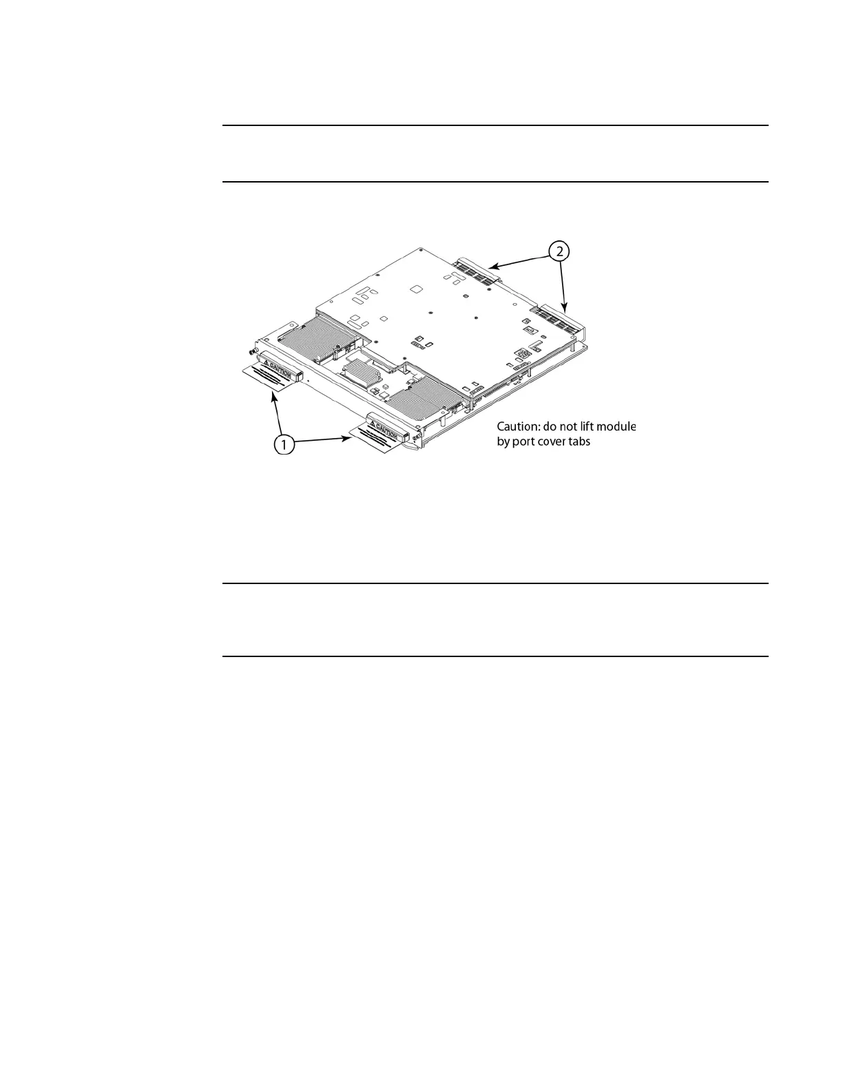
Do not use the port cover tabs to lift the module. They are not designed to support the weight
of the module, which can fall and be damaged.
FIGURE 90 Port covers and connector covers
6. Insert the module into the slot until the connectors securely engage the backplane.
In 4- and 8-slot devices, the modules are installed horizontally. In 16- and 32-slot devices the
modules are installed vertically. Figure 91 and Figure 92 show how to install 2x100G modules
in horizontal and vertical slots (4-slot and 16-slot devices are shown, but the process is the
same for 8-slot and 32-slot devices).
The 2x100G interface module is sensitive to dust and debris. Keep the optics covers in place
until you are ready to connect the fiber cable. Clean all fiber cables properly before you
connect them to the 2x100G interface module.
FIGURE 91 Installing 2x100G modules in a 4- or 8-slot device (4-slot shown)
 Loading...
