EasyManuals Logo

Brocade Communications Systems MLX Series Hardware Installation Guide

Brocade Communications Systems MLX Series
344 pages
To Next Page IconTo Next Page
To Previous Page IconTo Previous Page
Page #201 background imageLoading...
Page #201 background image
Brocade MLX Series and NetIron XMR Hardware Installation Guide 185
53-1003821-01
Installing a NetIron XMR 32000 router
3
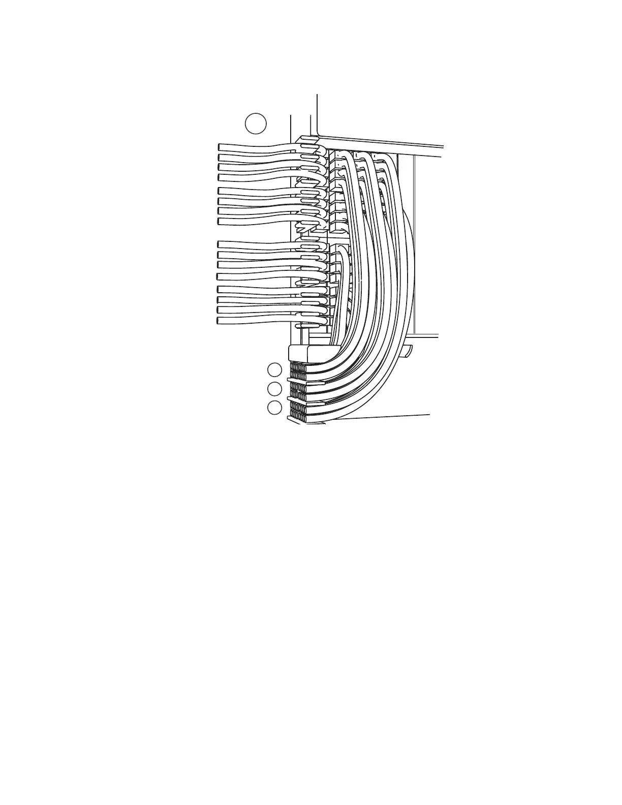
2. Route cables from slots #20 and #19 down through comb A. Refer to Figure 126.
3. Route cables from slots #22 and #21 down through comb B.
4. Route cables from slots #24 and #23 down through comb C.
Cable routing for the lower-right quadrant
1. Route cables from slots #32 and #31 directly to the right through the side comb. Refer to
Figure 127.
FIGURE 127 Routing the lower-right quadrant cables
1 Lower left quadrant 3 Comb B (slot #21 and #22 cables)
2 Comb A (slot #19 and #20 cables) 4 Comb C (slot #23 and #24 cables)
2
3
4
1

Table of Contents

Other manuals for Brocade Communications Systems MLX Series

Questions and Answers:

Question and Answer IconNeed help?

Do you have a question about the Brocade Communications Systems MLX Series and is the answer not in the manual?

Brocade Communications Systems MLX Series Specifications

General IconGeneral
BrandBrocade Communications Systems
ModelMLX Series
CategoryNetwork Router
LanguageEnglish

Related product manuals