Brocade MLX Series and NetIron XMR Hardware Installation Guide 289
53-1003821-01
Replacing fan assemblies
7
Removing the rear fan modules on a 32-slot router provides access to bus bars and the
backplane. Avoid contact with these parts. Hazardous energy levels exist at these locations.
3. Remove the fan assembly by grasping the handle on the faceplate and pulling the fan
assembly toward you. Pulling the fan assembly unseats the fan connector from the router.
Attaching the upward deflector
The upward deflector is placed between the fan assembly handle and the fan assembly faceplate.
To install the upward deflector to each fan assembly, complete the following steps:
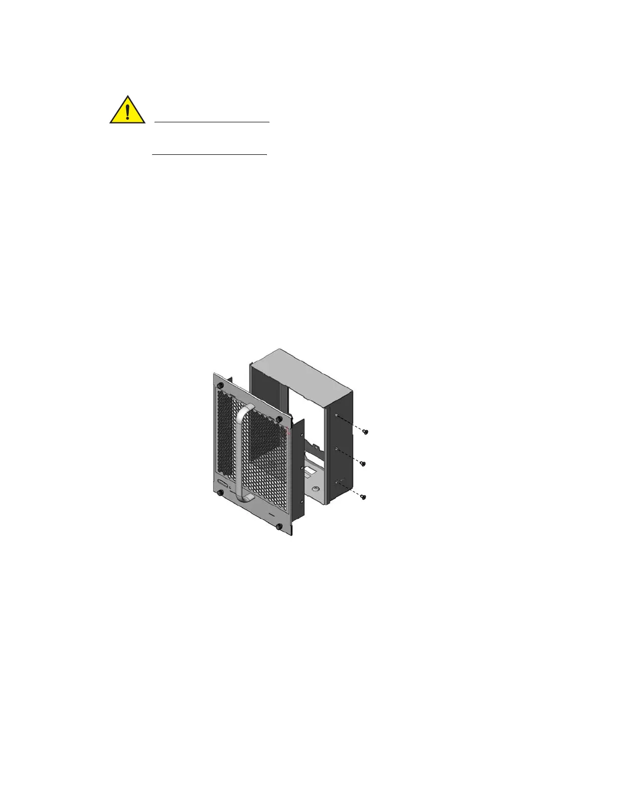
1. Using a Phillips screwdriver, detach the fan assembly faceplate by removing the three screws
from each side of the fan assembly. Refer to Figure 161 on page 283.
2. If present, remove and discard the tape that stabilizes louvers in some fan assembly models.
When present, the tape is located on the right and left sides of the fan assembly.
FIGURE 167 Removing the fan assembly faceplate
FIGURE 168 Removing tape from the fan assembly
 Loading...
