Brocade MLX Series and NetIron XMR Hardware Installation Guide 25
53-1003821-01
Router modules
1
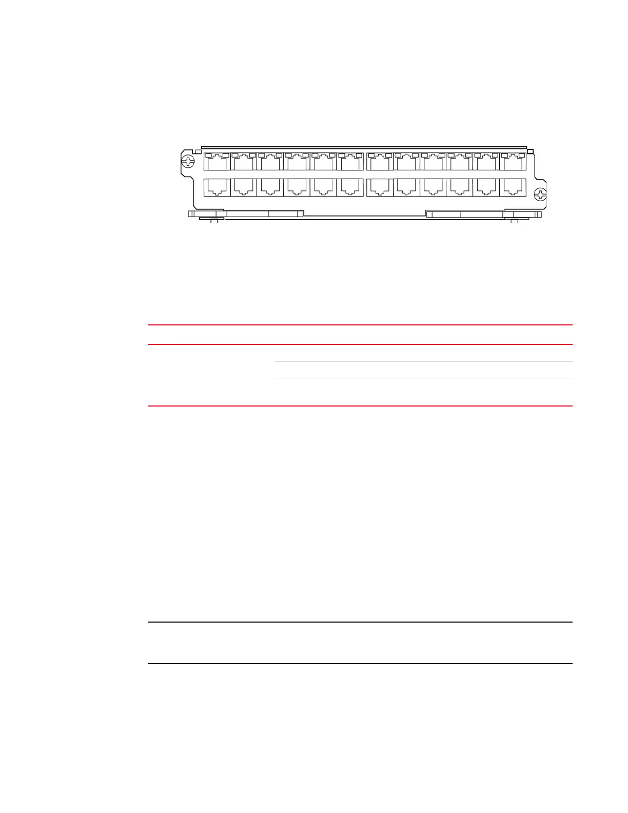
Figure 18 shows the front panel of the BR-MLX-1GCx24-X interface module.
FIGURE 18 BR-MLX-1GCx24-X copper interface module front panel
The front panel includes the following features:
• LEDs to the left support the top ports, LEDs to the right support the bottom ports
• 24 1 Gbps RJ45 copper ports
Table 10 describes the LEDs for the BR-MLX-1GCx24-X interface module.
Power supply requirements for BR-MLX-1GCx24-X interface modules
For power supply requirements for BR-MLX-1GCx24-X interface modules, refer to Chapter 8,
“Hardware Specifications”.
24-port 1 Gbps fiber interface module
The 24-port 1 Gbps fiber interface module is available in the following formats:
• BR-MLX-1GFx24-X
• BR-MLX-1GFx24-X-ML
The 24-port 1 Gbps fiber interface modules has 32 Mb of flash memory and provide 24 physical
ports, through which you can connect your router to other network routers. BR-MLX-1GFx24-X-ML
supports up to 512K IPv4 routes in hardware. BR-MLX-1GFx24-X supports up to 1M IPv4 routes in
hardware. The ML version can be upgraded to a X version through a software license. Please
contact Brocade to purchase the license upgrade.
24-port 1 Gbps fiber interface modules support 1 Gbps Copper SFP optics at 10 Mbps, 100Mbps
and 1Gbps speeds.
TABLE 10 BR-MLX-1GCx24-X copper module LEDs
Position State Meaning
LEDs located at top right and
left edge of top row ports. Left
LED for top port, right LED for
bottom port)
Solid green A link has been established.
Green blinking The port is transmitting and receiving packets.
Off No link exists and the port is not transmitting or
receiving packets.
 Loading...
