Brocade MLX Series and NetIron XMR Hardware Installation Guide 47
53-1003821-01
Installing 2x100GbE interface modules in Brocade MLX routers
2
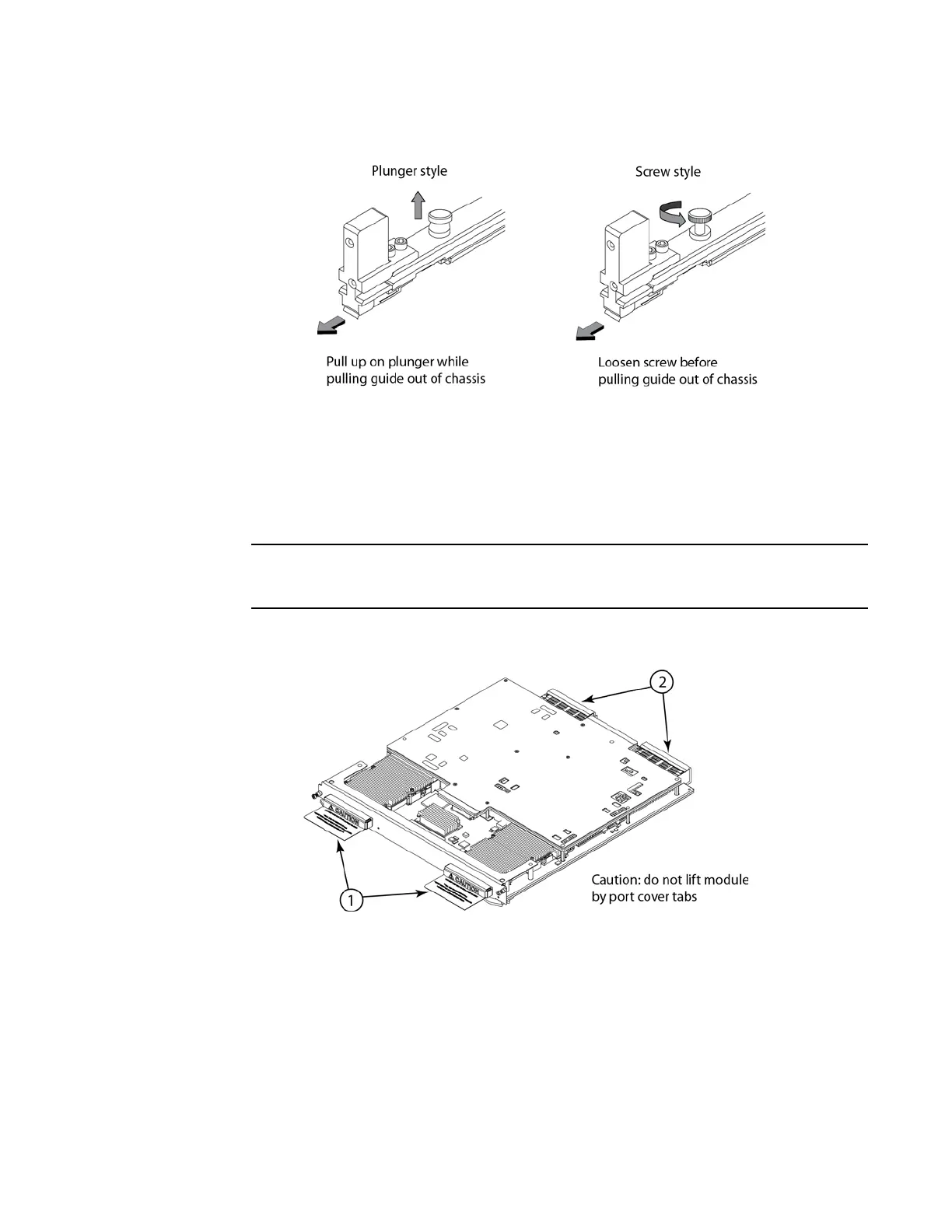
4. Remove the two connector covers from the rear connectors of the module. Refer to Figure 32.
5. Remove the port cover from one or both ports, depending on how you plan to use your module.
If you are using one port only (always Port 1), you must leave the port cover in the inactive port
(always Port 2). Port covers are designed for a tight fit and will take some effort to remove.
Refer to Figure 32.
Do not use the port cover tabs to lift the module. They are not designed to support the weight
of the module, which can fall and be damaged.
FIGURE 32 Port covers and connector covers
6. Insert the module into the slot until the connectors securely engage the backplane.
In 4- and 8-slot devices, the modules are installed horizontally. In 16- and 32-slot devices the
modules are installed vertically. Figure 33 and Figure 34 show how to install 2x100G modules
in horizontal and vertical slots (4-slot and 16-slot devices are shown, but the process is the
same for 8-slot and 32-slot devices).
 Loading...
