EasyManuals Logo

Brocade Communications Systems NetIron MLXe Series User Manual

Brocade Communications Systems NetIron MLXe Series
305 pages
To Next Page IconTo Next Page
To Previous Page IconTo Previous Page
Page #123 background imageLoading...
Page #123 background image
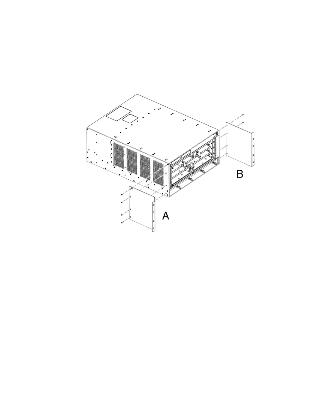
3. Attach the front mounting brackets to the chassis using eight 6-32 at head screws.
Brackets are marked with A or B. As you face the front of the EIA rack, A brackets must be installed on the left side, and B
brackets are installed on the right side. Do not mix A and B brackets. Refer to the following gure. The process is identical for 4-
slot and 8-slot routers.
FIGURE 46 Attach front mounting brackets to the router (MLXe-4 shown)
Mounting Brocade MLXe Series-4, -8, or -16 routers in a 4-post EIA rack
Brocade NetIron MLXe Series Hardware Installation Guide
53-1004203-04 123

Table of Contents

Questions and Answers:

Question and Answer IconNeed help?

Do you have a question about the Brocade Communications Systems NetIron MLXe Series and is the answer not in the manual?

Brocade Communications Systems NetIron MLXe Series Specifications

General IconGeneral
BrandBrocade Communications Systems
ModelNetIron MLXe Series
CategoryNetwork Router
LanguageEnglish

Related product manuals