The contents of this kit are listed in the following table.
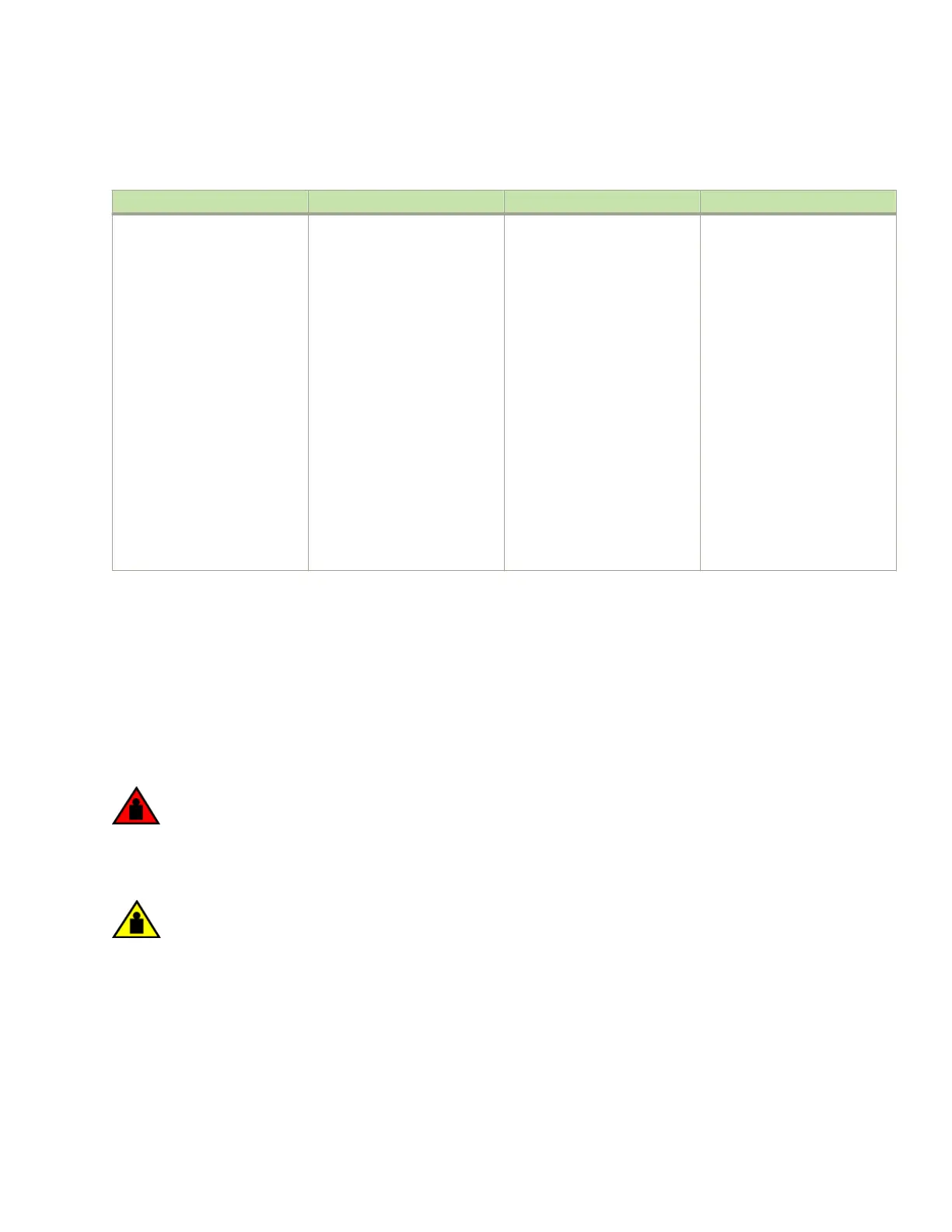
TABLE 34 Four-post ush-mount rack-mount kit contents
Part number Description Quantity Notes
49-1000166-XX
49-1000167-XX
42-1000901-XX
42-1000902-XX
52-1000278-01
42-0200036-XX
52-0000211-01
52-0000210-01
52-1000138-01
52-0200270-01
27-31" rail, left
27-31" rail, right
Rack mount bracket, left
Rack mount bracket, right
8-32 Phillips at-head screws,
black
Alignment Washer
10-32 X .63",Phillips Square
Cone Screw
Nut,retainer,10-32
M6 X 12MM, Phillips Square
Cone Screw
Floating Clip Nut, 10-32
1
1
1
1
10
16
16
16
16
16
Attaches the rack mount brackets
to the chassis.
Used with 52-1000138-01
(M6 Screws) to mount rails
49-1000166-XX and
49-100167-XX
Secure the chassis in the EIA
rack. Used in combination with
either 52-0000210-01 or
52-0200270-01, whichever is
appropriate for your rack type.
Used with part number
52-0000211-01.
Secures the left and right rails to
the EIA rack.
Used with part
52-0000211-01.
NOTE
Because of the weight of fully loaded routers, it is recommended that you mount the router in an EIA rack before
installing modules and power supplies.
You will need the following items to install your 32-slot router in a four-post EIA rack:
• A mechanical lift tool tted with a lift plate (instead of forks) to move the device o the pallet and transport it to the rack. The
lift should be rated for 500 lbs. minimum.
• A strap to secure and stabilize the device while it is being moved on the mechanical lift.
• No. 2 Phillips screwdriver
DANGER
Do not attempt to lift a Brocade MLX Series-32 chassis. It is extremely heavy. REMOVE THE POWER
SUPPLIES AND INTERFACE MODULES FIRST (management, switch fabric, and all line cards). Use a
mechanical lifting device to lift the chassis. Four or more people are required to position the unpopulated chassis
into the rack.
CAUTION
To prevent damage to the chassis and components, never attempt to lift the chassis using the fan or power supply
handles. These handles were not designed to support the weight of the chassis.
Before installation, plan the location and orientation of the device relative to other equipment in the rack. For cooling purposes,
allow a minimum of six inches of space between the front and back of the device, and walls or other obstructions.
Because you will need to use a mechanical lift to move and install the device, make sure you allow enough space to operate the
lift. You will also need at least two people to slide the router o the lift and into the rack.
NOTE
Installing a Brocade MLXe Series-32 router
Brocade NetIron MLXe Series Hardware Installation Guide
148 53-1004203-04

 Loading...