Brooks Automation 6. Service Procedures
Part Number: 603988 Rev. A
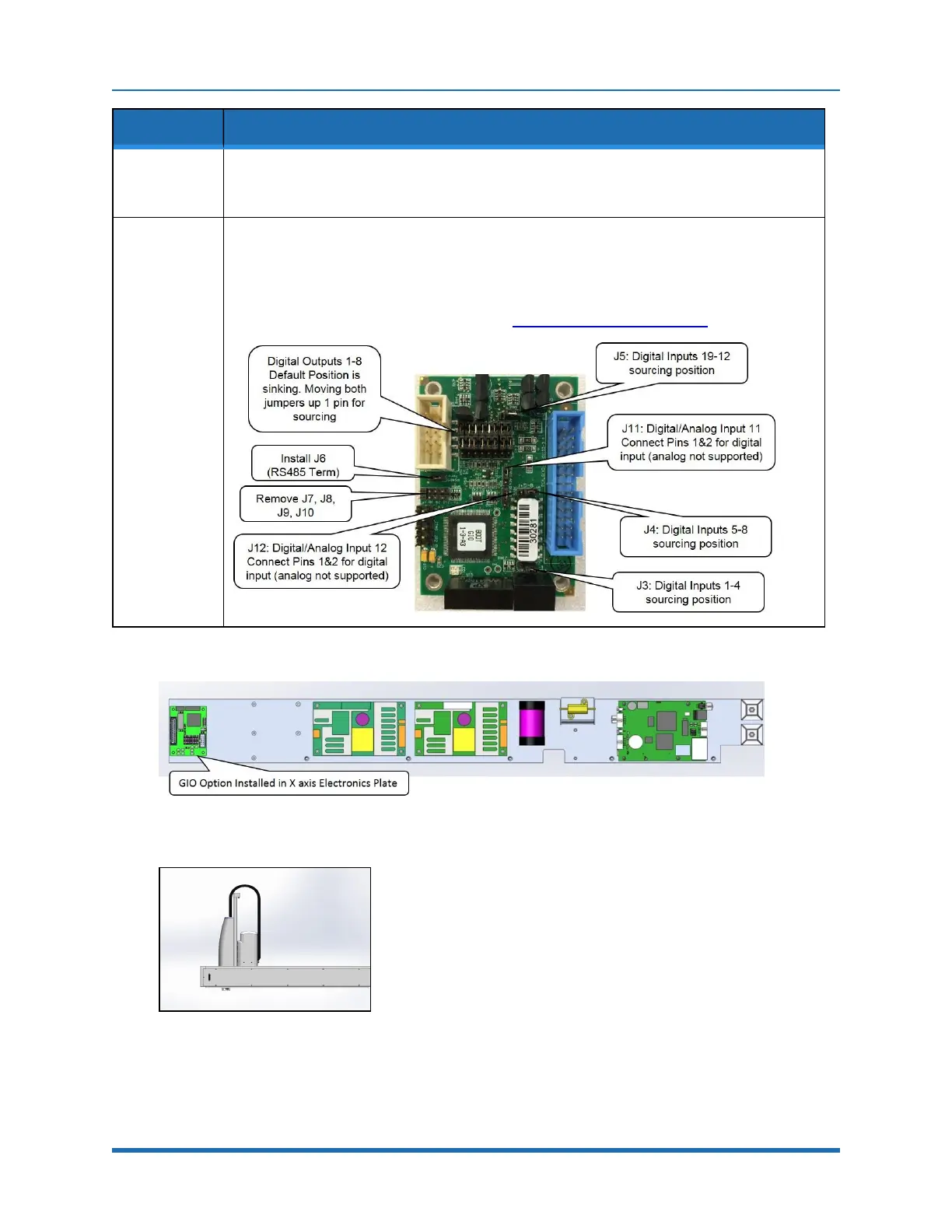
Installing the Optional GIO
Board
Step Action
10.
GIO signals may then be checked under Control Panels/Remote IO/Network Node 8.
Software addresses are described in the RS485 Remote IO Module (GIO) section.
Set other jumpers as desired for sourcing and sinking, see below.
11.
Attach rear panel.
For this GIO, it is configured as “GIO8” so the 8 outputs will be addressed as 800013-800020
and the 12 inputs will be addressed as 810001-8100012. See jumpers below.
Inputs and outputs are 24VDC with outputs limited to 100mA.
For pin assignments on the 25 pin Dsub, see “RS485 Remote IO Module (GIO”.
Figure 6-6: GIO Option Installed
Figure 6-7: GIO Board Installed
Copyright © 2023 Brooks Automation, Inc.
117