Brooks Automation 4. Hardware Reference
Part Number: 603988 Rev. A Robot Inputs and Outputs
Pin GPL Signal Number Description
5 GND
6 210001 Digital Input 1
7 210002 Digital Input 2
8 210003 Digital Input 3
User Plug Part No Amp 794617-8, crimp contacts 1-794611-2
RS485 Remote IO Module (GIO)
Customers who need additional digital IO may order the RS485 Remote IO Module. This module
installs in the X-axis of the robot and provides 12 Digital Inputs and 8 Digital Outputs in a 25-pin
Dsub connector.
The RS485 Remote IO Module (GIO) provides 12 general-purpose optically isolated digital input
signals and 8 general-purpose optically isolated digital output signals. Two inputs, 11 and 12, can
be optionally configured as analog inputs by means of jumpers J1 and J2. Connecting J1 to pins 1
and 2 (default) configures these inputs as digital and connecting pins 2 and 3 configures them as
analog. These input and output signals are intended for interfacing to tooling and sensors or for
general application needs. This board is connected to the controller by an RS485 serial line that
allows the controller to scan the GIO I/O with a nominal period of 4 milliseconds.
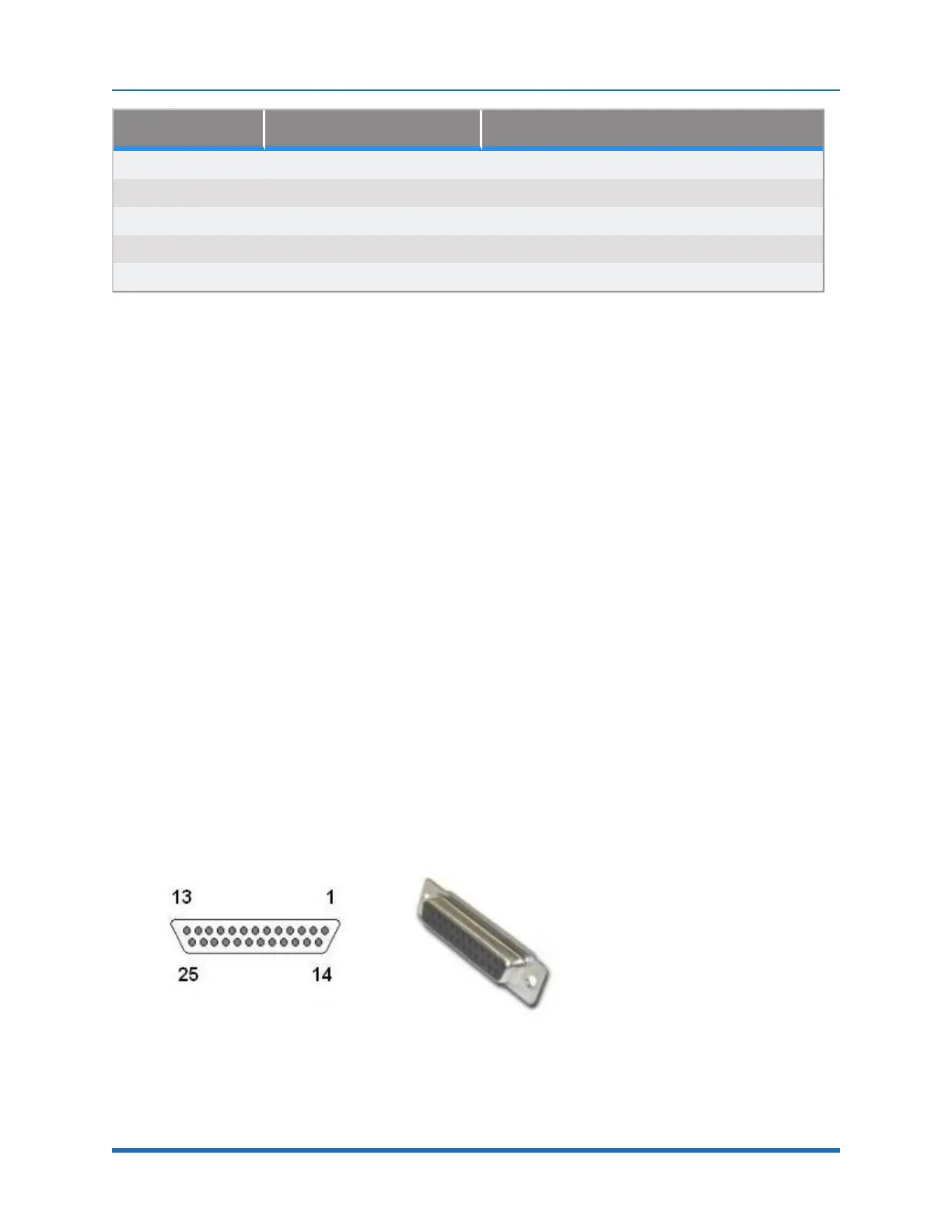
The DIO signals are accessible via the DB25 female connector (Figure 4-20 and Table 4-4)
mounted on the facilities panel when this option is ordered. The DIO signals addresses are
determined by a base address set by a DIP switch on the DIO board. For the PF400 robot without
the linear axis option the DIO option is located at the robot connector panel and for both this location
and also for the location at the end of the optional linear axis, all the address jumpers will NOT be
installed, which sets the address of this module to “8.” This address avoids conflicts with other
RS485 network controllers for the gripper and optional linear axis. See “"Installing the Optional GIO
Board"” under "Service Procedures" for details on installing this module.
The software addresses will then be as follows.
Figure 4-20: DB25 Female
Copyright © 2023 Brooks Automation, Inc.
67