Confidential
5-85
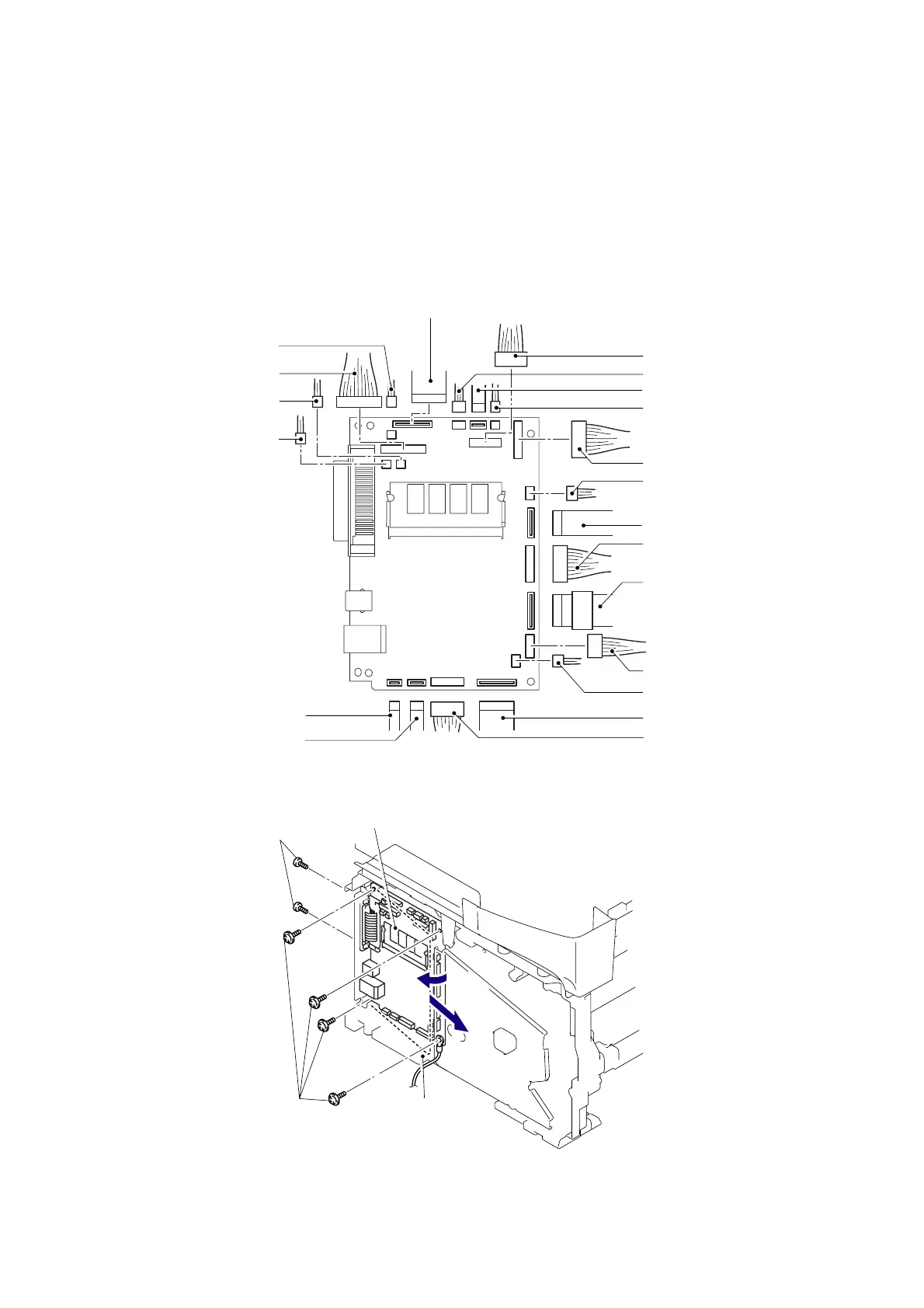
5.1.65 Main PCB
(1) Disconnect the 12 connectors and 7 flat cables from the Main PCB.
NOTE:
- After disconnecting flat cable(s), check that each cable is not damaged at its end or short-
circuited.
- When connecting flat cable(s), do not insert them at an angle. After insertion, check that
the cables are not at an angle.
Fig. 5-120
(2) Remove the four cup S M3x6 Taptite screws and two Screws to remove the Main PCB.
Fig. 5-121
Engine PCB connector
Relay rear (Flat cable)
FB cover sensor connecto
Main PCB
Screws
Taptite, cup S M3x6
FG harness
2a
2b
Wireless LAN connecto
(For the model with the Wireless
LAN only)
Polygon motor (Flat cable)
LVPS PCB connecto
Main motor (Flat cable)
Thermistor connecto
HVPS PCB (Flat cable)
LT connecto
Relay front (Flat cable)
Battery connecto
(For the model with
the battery only)
Engine PCB connector
CCD module (Flat cable)
Speaker connecto
CU connecto
(For the models with the NCU only)
Home position connecto
LD harness (Flat cable)
DX solenoid connecto
(For the models
with the DX only)
Panel PCB connecto
 Loading...