4-49
Confidential
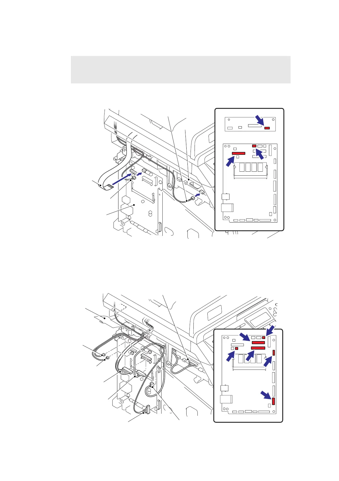
(18) Connect the connectors of the Home position sensor harness and FFC cable into the
Main PCB.
(19) Connect the connector of the Scanner motor harness into the Driver PCB.
Fig. 4-77
(20) Connect the six connectors of the each harness into the Main PCB.
(21) Hang the Hook of the Harness guide film, and Bind up the each harness.
Fig. 4-78
Note :
• When connecting flat cable(s), do not insert them at an angle. After insertion, check
that the cables are not at an angle.
Driver PCB
Driver PCB
Scanner motor
harness
FFC
Home position sensor harness
Main PCB
Main PCB
Driver PCB
Driver harness
NCU harness
Panel PCB harness
USB HOST
harness ASSY
Main PCB
Speaker harness
Harness guide film
Battery harness
 Loading...