4-9
Confidential
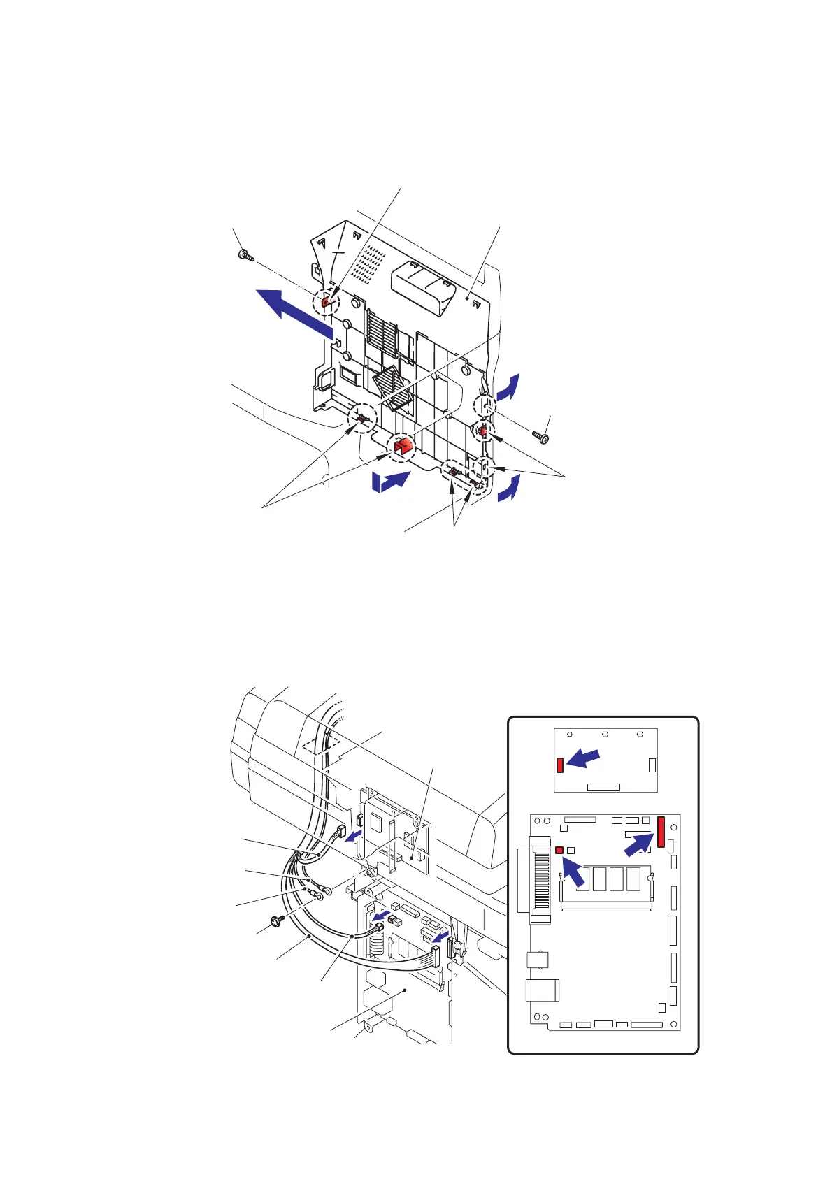
(15) Remove the two bind B M4x12 Taptite screws, and release the Hooks by following
direction from 15a to 15d, then remove the Side cover R.
Fig. 4-11
(16) Remove the cup S M3x6 Taptite screw, remove the ADF FG harness and FB FG harness.
(17) Disconnect the Connector from the Driver PCB.
(18) Disconnect the two Connectors from the Main PCB.
Fig. 4-12
Taptite bind B M4x12
Hook
Hooks
Hooks
Side cover R
Hook
Taptite bind B M4x12
15d
15c
15b
15a
Driver PCB
Main PCB
Main PCB
Driver PCB
<Left side>
Connector
(ADF motor harness)
Connectors
(ADF relay harness)
Connector (FB cover sensor)
FB FG harness
Taptite cup S M3x6
ADF FG harness

 Loading...