Section04FUELSYSTEM
Subsection 03 (DPM SYSTEM)
1
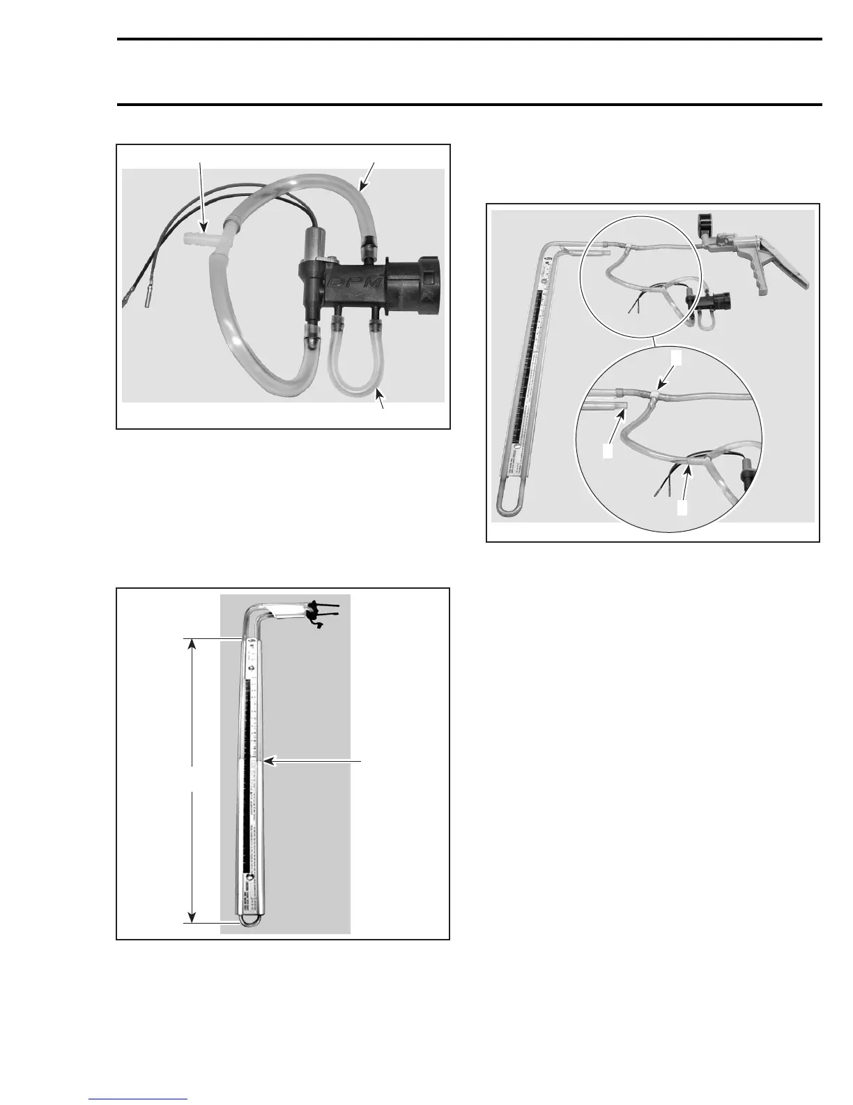
A32C6UA
23
1. 3.5 mm (9/64 in) ID hose
2. 6.0 mm (15/64 in) ID hose
3. 6.0 mm (15/64 in) T-fitting
Water Column Preparation
Mount water column vertically and secure it to a
wall or workbench.
Fillwatercolumntocenterline(atleast175mm
(6-7/8 in)) in height. Refer to following photo.
A02C2ZA
1
A
1. Center line at 175 mm (6-7/8 in)
A. 350 mm (13-3/4 in)
Connecting the Pump, DPM Manifold
and Water Column
Connect hoses as shown.
A32C6YA
1
3
2
1. 4.8 mm (3/16 in) T-fitting
2. T-fitting
3. Vented to atmosphere
Collect hose into one of the water column tubes,
leave the other tube at atmospheric pressure.
Testing
Set pump to «vacuum».
CAUTION: Never use pump directly on DPM to
make a pressure test. The vacuum produced
by the pump is too high and would damage
DPM components. Use the water column as
explained above.
Apply negative pressure (vacuum) until the ex-
tremities of the water in the tube attain a differ-
ence of 350 mm (13-3/4 in).
Stop pumping and allow water levels to stabilize
in tube.
Analysis
If water level remains unchanged, the DPM man-
ifold is not defective.
If water level drops slowly to return to an even
level in more than 10 seconds, the DPM manifold
is not defective.
mmr2005-104 197