Section 09 REAR SUSPENSION
Subsection 03 (SC 4 SUSPENSION)
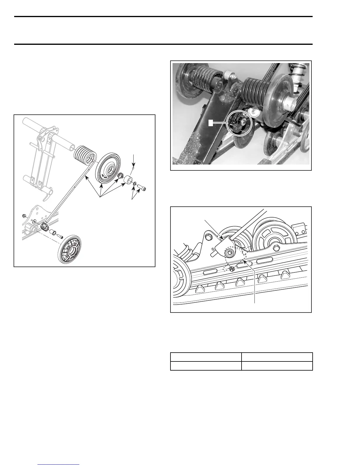
Loosen set screw from locking rings.
Remove the following on both sides:
– locking ring
– axle spring
– top idler wheel
– rear spring.
A33F5OB
1
3
2
ON BOTH SIDES
1. Remove screws
2. Loosen set screw
3. Remove the following
REAR SPRING INSTALLATION
Installation is reverse of removal procedure. Pay
attention to the following details.
At assembly, respect THIS SIDE OUT inscription
on top idler wheels.
At assembly, make sure that spring end is in cam
adjuster.
A33F5QA
1
ON BOTH SIDES
1. Spring end in cam adjuster
CAUTION: To avoid track damage, spring sup-
ports must be mounted upward.
A03F0VA
1
2
TYPICAL — RIGHTSIDESHOWN
1. Right position: upward
2. Wrong position
Respect the following tightening torque specifica-
tion:
DESCRIPTION TIGHTENING TORQUE
Locking ring set screw 2.5 N•m(22lbf•in)
SLIDER SHOE VERIFICATION
Molding line is the wear limit indicator.
416 mmr2005-096