Section 08 DRIVE SYSTEM
Subsection 03 (DRIVEN PULLEY)
A03D2SA
1
2
2
2
1
1
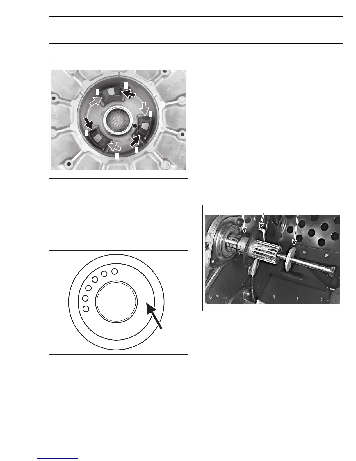
1. BLACK slider shoe
2. RED slider shoe
Assemble driven pulley components by reversing
the disassembly procedure.
Cam and Spring
Make sure to install proper cam. Refer to TECH-
NICAL DATA.
Cam angle is identified on cam.
B
O
M
B
A
R
D
I
E
R
6
5
4
3
2
1
44°
A24D06A
Install spring no. 6 in sliding half with its end in-
serted in hole B.
Position cam no. 5 then insert spring in adjusting
hole no. 2 into outer cam.
IMPORTANT: With the spring ends at positions
B and 2, spring preload is equal to zero (0). To
work properly, the driven pulley must have a zero
preload.
Compress outer cam using the clutch spring com-
pressor (P/N 529 035 524). Install washer no. 4
then secure outer cam with circlip no. 3.
CAUTION: Ensure that circlip is properly insert-
ed into shaft groove and that spacer recess is
facing circlip.
INSTALLATION
Countershaft
Apply Loctite antiseize lubricant (P/N 293 800 070)
on countershaft splines.
CAUTION: Always apply antiseize on the coun-
tershaft before final pulley installation to pre-
vent a possible seizing up between pulley and
countershaft.
Make sure that spacer no. 2 is on countershaft
no. 1 before installing driven pulley. Note also that
washer shoulder is facing driven pulley.
A30D14A
1 23
TYPICAL
1. Spacer
2. Shoulder on this side
3. Concavesidefacingdrivenpulley
Should installation procedure be required, refer to
BRAKE then look for BRAKE DISC and COUNTER-
SHAFT BEARING ADJUSTMENT.
Reinstall the pulley on the countershaft by revers-
ing the removal procedure.
Pulley Retaining Screw
Torque pulley retaining screw no. 14 to 25 N•m
(18 lbf•ft).
mmr2005-088 343