Section 09 REAR SUSPENSION
Subsection 03 (SC 4 SUSPENSION)
At installation, rear arm stroke limiter must be on
rear side.
Insert dowel pin into pivot arm hole, dowel pin
must exceed block guide by 2 to 2.3 mm (.079 to
.091 in).
Respect the following tightening torque specifica-
tions.
DESCRIPTION TIGHTENING TORQUE
Pivot arm/runners nut 25 N•m(18lbf•ft)
Locking ring set screw 2.5 N•m(22lbf•in)
BLOCK INSTALLATION
Both blocks are identified R or L (right or left) and
have position number (from 1 to 4). At installation
make sure to install proper block on proper side
withthesameadjustmentpositiononbothsides.
A33F60A
1
2
TYPICAL
1. Blocks are identified R or L (right or left)
2. Blocks position number (from 1 to 4)
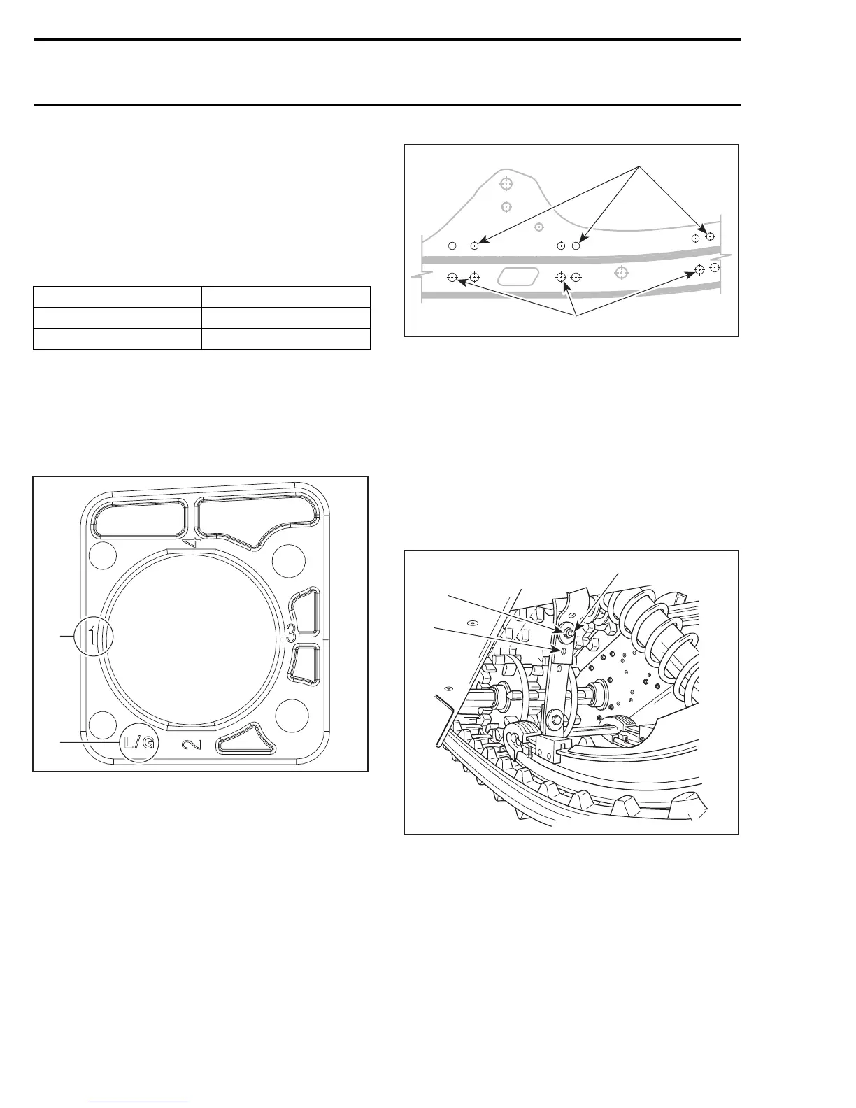
IDLERWHEELSINSTALLATION
Refer to illustration for idler wheels position at in-
stallation.
A33F5ZA
1
2
1. RH side wheels position
2. LH side wheels position
STOPPER STRAP
Inspect strap for wear or cracks, bolt and nut for
tightness. If loose, inspect hole for deformation.
Replace as required.
Make sure it is attached through proper hole from
the end.
Torquenutto11N•m(97lbf•in).
A32F3DA
A
1
2
TYPICAL
1. 1
st
hole
2. 2
nd
hole
A. 11 N•m(97lbf•
in)
RIDE ADJUSTMENT
Refer to the appropriate Operator’s Guide.
420 mmr2005-096