Section 06 ENGINE MANAGEMENT (SDI)
Subsection 03 (COMPONENT INSPECTION, REPLACEMENT AND ADJUSTMENT)
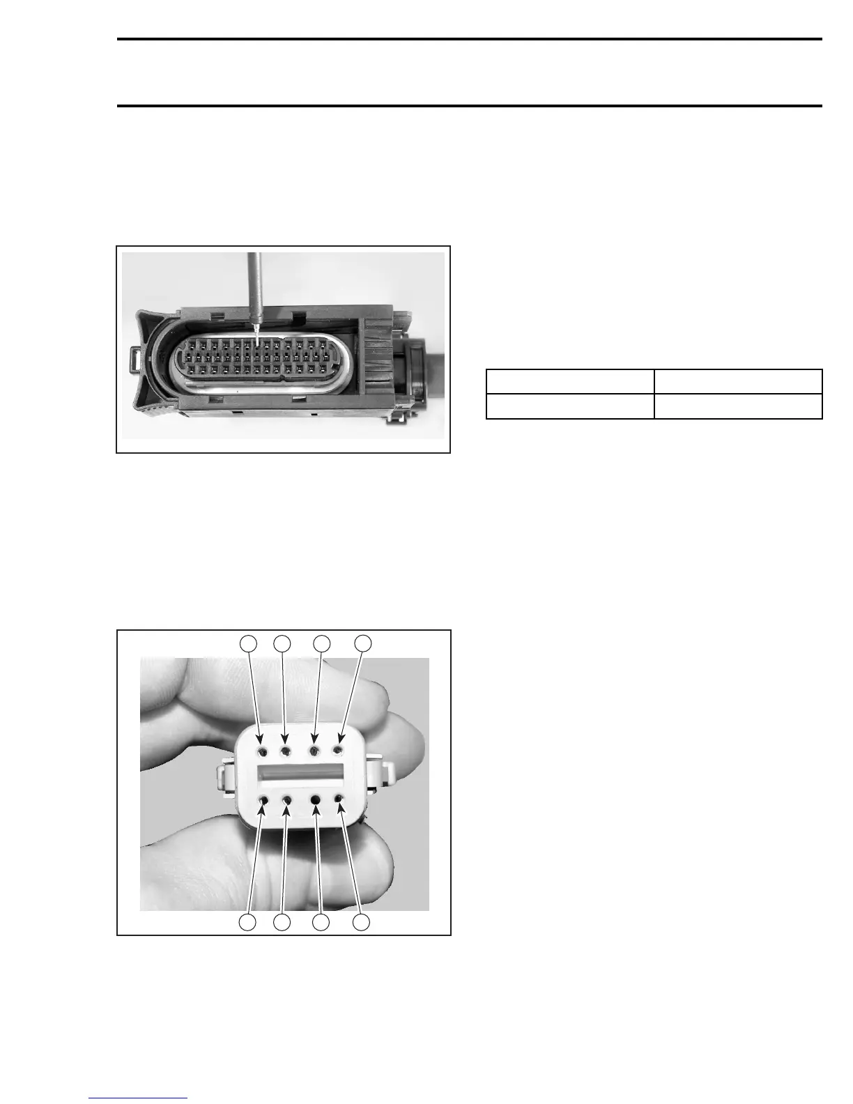
CAUTION: Probe on top of terminal only. Do
not try to probe inside terminal or to use a pa-
per clip to probe inside terminal, it will dam-
age the square-shaped terminal and this could
lead to improper function of the engine man-
agement system.
A32CCPA
PROBE ONLY ON THE PIN NOZZLE OF FEMALE CONNECTOR
CAUTION: Do not disconnect the ECM connec-
tor needlessly. They are not designed to be dis-
connected/reconnected repeatedly.
Engine Connector
Use this illustration to locate the pin numbers on
the engine connector of the wiring harness when
performing tests.
6
A32C9IA
7
8
5
1
2
34
ENGINE CONNECTOR PIN-OUT (WIRING HARNESS SIDE)
RELAY
Relay 2
Connect vehicle communication kit (VCK) and use
B.U.D.S. software.
Energize relay 2 from Activation tab.
Listen to or touch relay to feel it click.
If the relay does not work, disconnect the connec-
tor from the relay to test the input side.
Connect a voltmeter as indicated in the following
table.
TEST PROBE (+) TEST PROBE (-)
RED/GRAY wire
Battery ground
Battery voltage (12 V) should be read.
If voltage reads 12 V, check continuity of OR-
ANGE/GREEN wire between relay connector
and pin B-16 of ECM connector. If faulty, repair
wire/connector. If wire/connectors test good, try
anewECM.
If voltage does not read 12 V, check continuity
of wire on supply side of relay. If faulty, repair
wire/connector. If wire/connectors test good, re-
fer to ELECTRICAL SYSTEM to test output side or
relay.
mmr2005-081 253