Section 03 ENGINES
Subsection 04 (MAGNETO SYSTEM)
STATOR
Inspection
Always check stator no. 3 before changing it. Re-
fer to CHARGING SYSTEM.
Cleaning
Clean all metal components in a non-ferrous metal
cleaner.
CAUTION: Clean stator using only a clean cloth.
Removal
Remove:
– magneto flywheel no. 1
– all Allen socket screws no. 4 retaining stator to
magneto housing
– grommet from crankcase where CPS/trigger
coils no. 5 and stator wires exit magneto hous-
ing.
Unplug the CPS/trigger coil connectors and pull
the wires through the grommet location.
NOTE: To pass the stator connector into the grom-
met location it is necessary to pass the CPS/trig-
ger coil connector first.
Unplug the stator connectorand remove the stator
no. 3.
Installation
Insert the stator connector into crankcase grom-
met then the CPS/trigger coil connector(s).
Install the grommet on crankcase
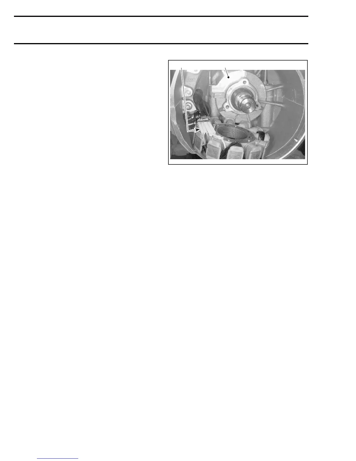
Position stator no. 3 so that its wire protectors are
over crankcase recess.
1
A32E0KA
2
1. Crankcase recess
2. Wire protectors
NOTE: During installation, make sure the stator
harness is located on the left side.
Apply Loctite 243 (blue) (P/N 293 800 060) on
threads of stator screws then torque them to
9N•m(80lbf•in).
Reinstall all other removed parts.
CPS/TRIGGER COIL
Inspection
Always check CPS or trigger coils before changing
it. Refer to iGNITION SYSTEM.
Removal
NOTE: Always check CPS or trigger coils no. 5 be-
fore changing them. Refer to OVERVIEW section.
To replace the CPS or the trigger coil(s), remove
or disconnect the following:
– magneto flywheel no. 1
– air intake silencer to allow an access to the
CPS/trigger coil connectors (if necessary)
– trigger coil connector housing(s)
– grommet from crankcase where CPS/trigger
coil wire(s) exit(s) magneto housing
– retaining screws no. 6
– CPS or trigger coil(s) and carefully pull wires.
Installation
For installation, reverse the removal procedure.
78 mmr2005-071