Section 09 REAR SUSPENSION
Subsection 02 (SC 3 SUSPENSION)
1
A32F15A
2
1. Protrusion
2. Stoppers
Dowel pin must exceed block guide by 2 to 2.3
mm(.079to.091in).
At installation, insert dowel pin into pivot arm hole.
2
A32F14A
13
LEFT SIDE SHOWN
1. Dowel pin
2. Pivot arm hole
3. «L» identification for left side
Respect the following tightening torque specifica-
tions:
DESCRIPTION TIGHTENING TORQUE
Locking ring set screw 2.5 N•m(22lbf•in)
Pivot arm lower nut 24.5 N•m(18lbf•ft)
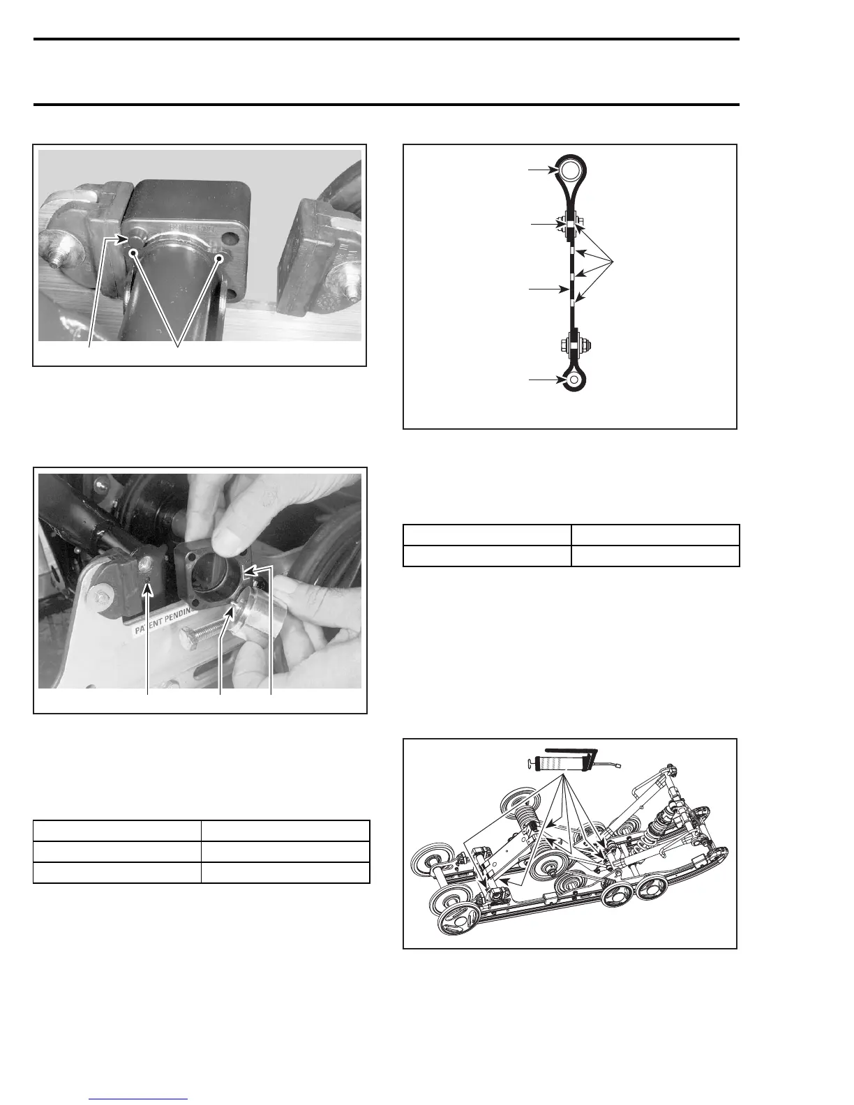
STOPPER STRAP
Inspect strap for wear or cracks, bolt and nut for
tightness. If loose, inspect hole for deformation.
Replace as required.
Make sure it is attached through proper hole from
the end.
A33F6BA
Position
4-1
1
3
2
1. Front arm (top)
2. Front axle
3. Rear of vehicle
Respect the following tightening torque specifica-
tion:
DESCRIPTION TIGHTENING TORQUE
Stopper strap nuts
11 N•m(97lbf•in)
RIDE ADJUSTMENT
Refer to the appropriate Operator’s Guide.
LUBRICATION
Lubricate front and rear arms at grease fittings
using suspension synthetic grease (P/N 293 550
033).
A33F68A
TYP
ICAL
406
mmr2005-095