Section 09 REAR SUSPENSION
Subsection 02 (SC 3 SUSPENSION)
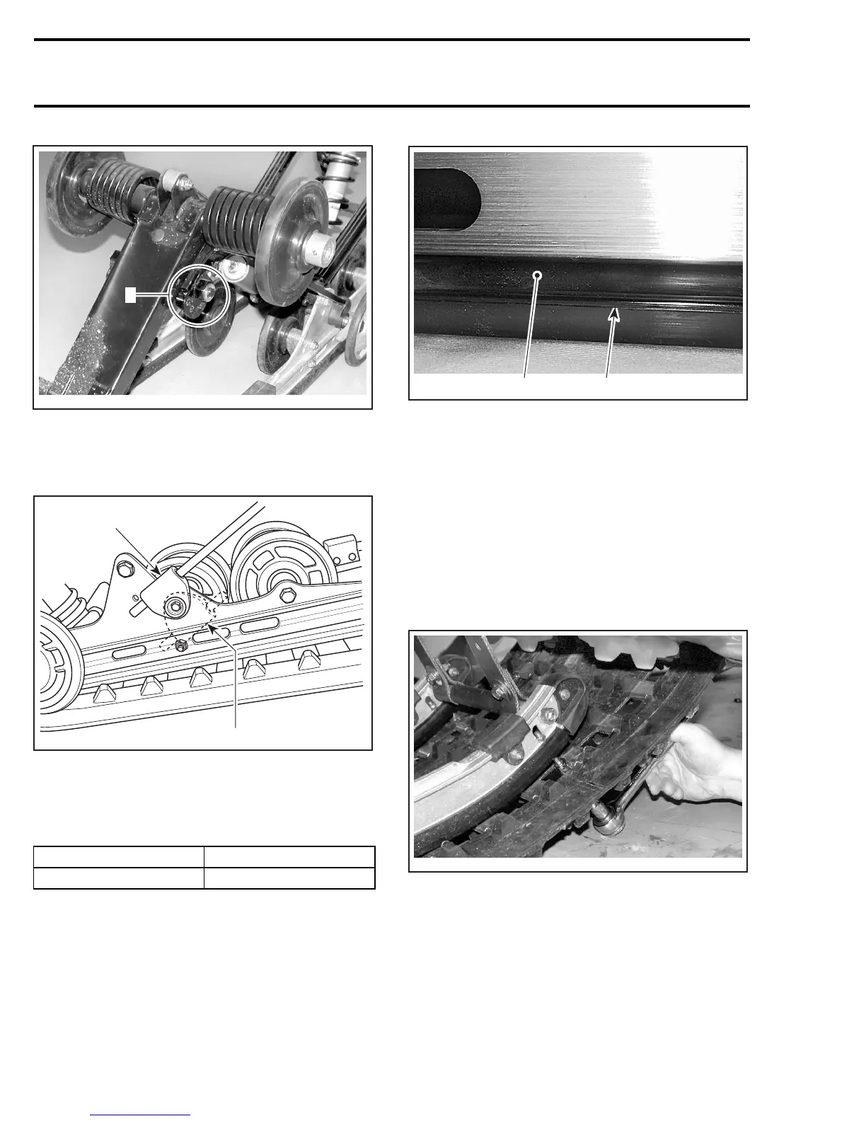
A33F5QA
1
ON BOTH SIDES
1. Spring end in cam adjuster
CAUTION: To avoid track damage, spring sup-
ports must be mounted upward.
A03F0VA
1
2
TYPICAL — RIGHTSIDESHOWN
1. Right position: upward
2. Wrong position
Respect the following tightening torque specifica-
tion:
DESCRIPTION TIGHTENING TORQUE
Locking ring set screw 2.5 N•m(22lbf•in)
SLIDER SHOE VERIFICATION
Molding line is the wear limit indicator.
1
A03F3SA
2
TYPICAL
1. Slider shoe
2. Molding line (wear limit indicator)
Replace slider shoes when wear limit is reached.
CAUTION: Slider shoes must always be re-
placed in pairs.
SLIDER SHOE REMOVAL
Lift rear of vehicle and support it off the ground.
Completely loosen track tension.
Remove front runners nut and screw.
A33F5RA
TYPICAL — REMOVE NUT AND SCREW
Align track window with slider shoe.
402 mmr2005-095