Section 03 ENGINES
Subsection 07 (ENGINE MEASUREMENT)
F01D0KA
1
A
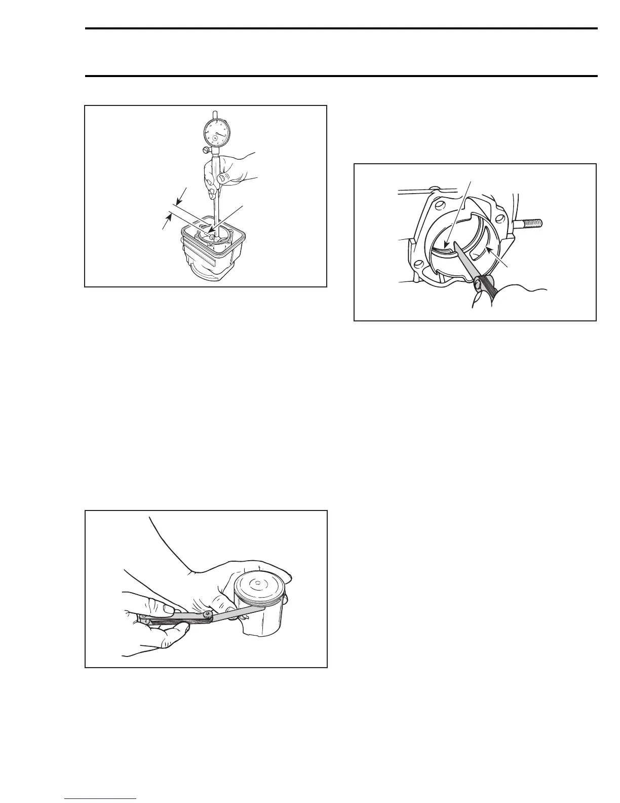
1. Measuring perpendicularly (90°)topistonpinaxis
A. 16 mm (5/8 in)
Read the measurement on the cylinder bore
gauge. The result is the exact piston/cylinder
wall clearance. If clearance exceeds specified
tolerance, replace cylinder or rebore and install
oversize piston depending on engine.
NOTE: Make sure the cylinder bore gauge indica-
tor is set exactly at the same position as with the
micrometer, otherwise the reading will be false.
RING/PISTON GROOVE
CLEARANCE
Using a feeler gauge check clearance between
rectangular ring and groove. Replace piston if
clearance exceeds specified tolerance.
A01C0PA
RING END GAP
Position ring half-way between transfer ports and
intake port.
NOTE: In order to correctly position the ring in the
cylinder, use piston as a pusher.
Using a feeler gauge, check ring end gap. Replace
ring if gap exceeds specified tolerance.
A01C0QA
2
1
1. Transfer port
2. Intake port
CRANKSHAFT DEFLECTION
Crankshaft deflection is measured with a dial indi-
cator.
Measuring (in crankcase)
First, check deflection with crankshaft in
crankcase. If deflection exceeds the specified tol-
erance, recheck deflection using V-shaped blocks
to determine the defective part(s). See below.
Measuring (on bench)
Once engine is disassembled, check crankshaft
deflection on V-shaped blocks. If deflection
exceeds the specified tolerance, it can be worn
bearings or a bent crankshaft. Remove crankshaft
bearings and check deflection again on V-shaped
blocks to determine the defective part(s). See
measurement A in following illustration.
mmr2005-103 133