Section 03 ENGINES
Subsection 03 (ENGINE REMOVAL AND INSTALLATION)
A33C2GA
1
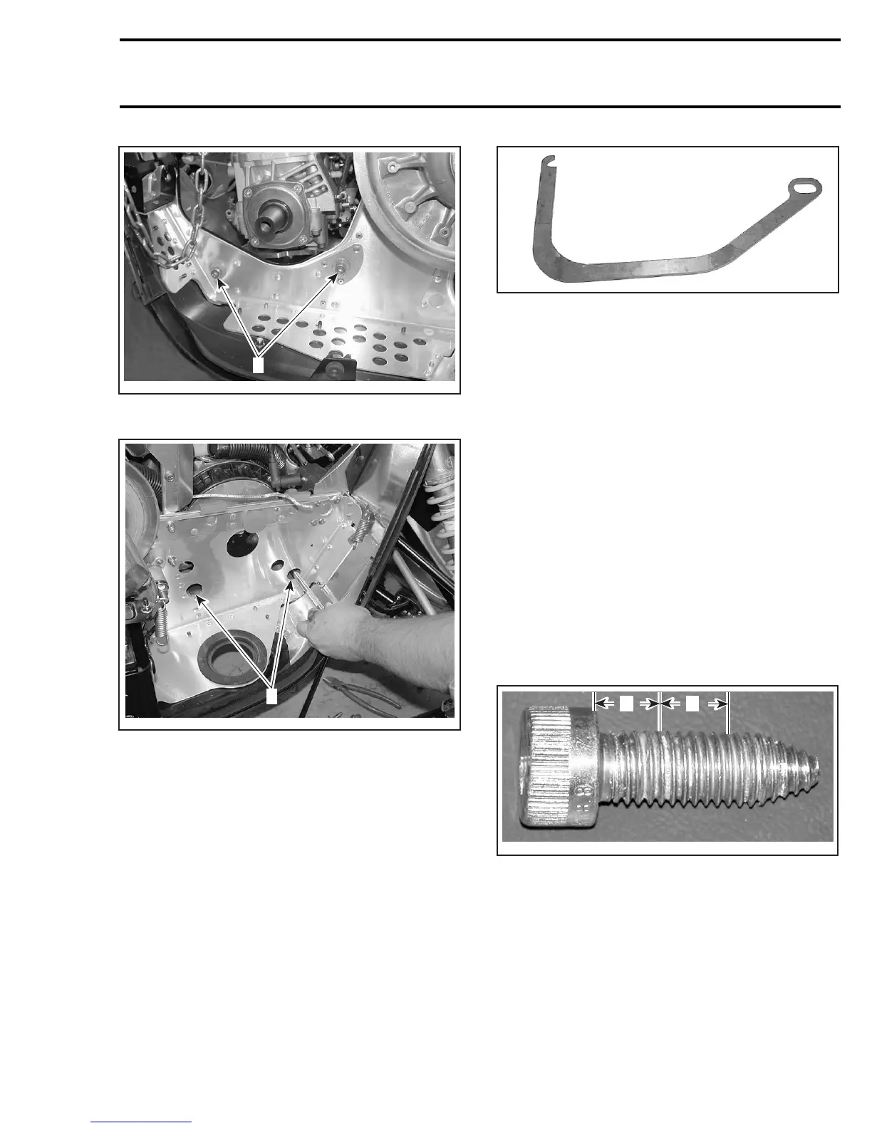
LEFT SIDE OF VEHICLE
1. Engine support bolts
A33C2HA
1
RIGHTSIDEOFVEHICLE
1. Holes to reach engine support bolts
Unscrew the engine stopper no. 2 completely.
Lifttheenginealittlethenunplugoilpumphoses
and the crankcase vent hose.
On SDI models, disconnect all engine connectors
(CPS, WTS, KS and injectors).
Lift and slide out engine using the engine removal
hook (P/N 529 035 829).
529 035 829
Unscrew engine support nuts no. 3 then separate
support no. 4 from engine.
INSPECTION
Check if engine support no. 4 is cracked, bent or
otherwise damaged. Replace if necessary.
Check rubber mounts no. 5 on engine support.
Replace them if brittle, cracked or otherwise dam-
aged.
INSTALLATION
To install engine in vehicle, reverse the removal
procedure. However, pay attention to the follow-
ing.
Install engine support under engine then torque
engine support nuts to 35 N•m(26lbf•ft).
Before installing engine support bolts no. 1,apply
Loctite 243 (blue) (P/N 293 800 060) as shown in
the following illustration.
A33C2IA
A
B
A. DonotapplyLoctiteinthisarea,±10mm(.39in)
B. Loctite area, ± 8 mm (.31 in)
Torque engine support bolts to 48 N•m(35lbf•ft).
Hand torque engine stopper no. 2 then torque its
nut no. 6 to 50 N•m(37lbf•ft).
Reinstall all removed parts by using the appropri-
ate component/system reinstallation procedures
described in this shop.
mmr2005-070 69