Section 09 REAR SUSPENSION
Subsection 02 (SC 3 SUSPENSION)
NOTE: If necessary, to ease shock removal, un-
fasten one end of stopper straps to release shock
pressure.
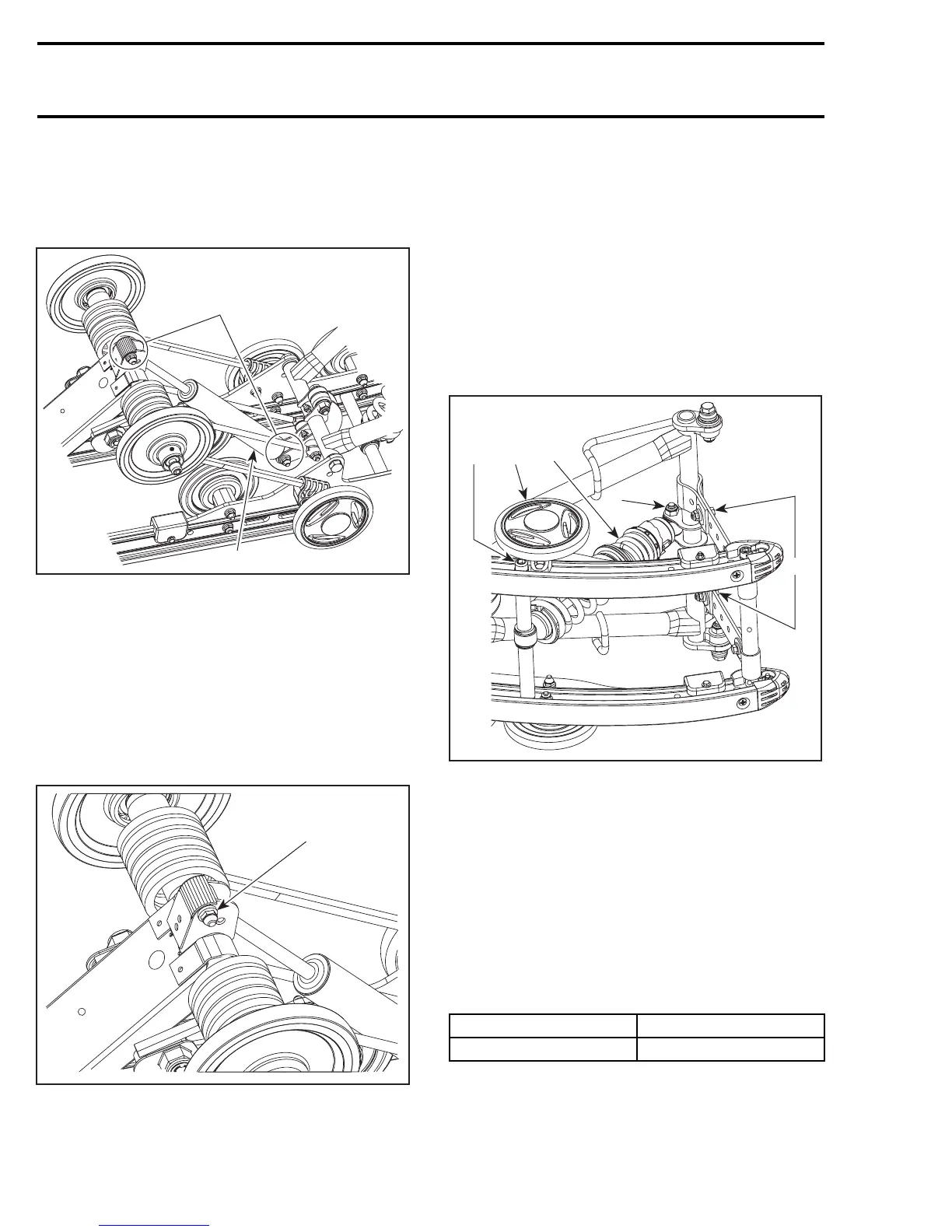
Remove rear arm shock.
A33F65A
1
2
TYPICAL
1. Upper/lower bolt and nut
2. Rear shock absorber
REAR SHOCK ABSORBER
INSTALLATION
Installation is reverse of removal procedure.
CAUTION: Take care not to damage grease fit-
ting.
A33F66A
1
REAR SHOCK ABSORBER POSITION
1. Shock installed using upper hole
FRONT SHOCK ABSORBER
REMOVAL
Lift rear of vehicle and support it off the ground.
Unfasten one end of stopper straps to release
shock pressure.
Unbolt front shock from the top.
Remove the front idler wheels to gain access to
the axle retaining self-locking screws.
Unbolt axle screws and slide out axle to remove
shock.
A33F67A
3
2
1
5
4
TYPICAL
1. Front shock upper bolt and nut
2. Idler wheel
3. Axle screw
4. Unfasten one end of stopper straps
5. Front shock
FRONT SHOCK ABSORBER
INSTALLATION
Installation is reverse of removal procedure.
Respect the following tightening torque specifica-
tion:
DESCRIPTION TIGHTENING TORQUE
Stopper strap(s) nuts 11 N•m(97lbf•in)
REAR SPRING REMOVAL
Lift rear of vehicle and support it off the ground.
400 mmr2005-095