Section 03 ENGINES
Subsection 02 (EXHAUST SYSTEM)
Fan Cooled Engines
Apply RTV sealant (P/N 293 800 090) on gasket
contact surfaces.
All Engines
Install all exhaust springs using exhaust spring in-
staller/remover (P/N 529 035 401).
MANIFOLD
Removal
Remove:
– tuned pipe no. 2
– doughnut shaped exhaust gasket no. 3
– manifold screws no. 5
CAUTION: On engines with 6 mm (1/4 in)
screws, heat screws for 30 seconds before
loosening to prevent screw breakage.
– manifold no. 6
– gaskets no. 7.
Inspection
Check if the manifold is cracked or damaged. Re-
place if necessary.
Installation
Install the manifold with new gaskets.
Torque manifold screws no. 5.
NOTE: On liquid cooled engines, use the following
tightening sequence.
1-9
A33C3VA
23
6
4
7
8
5
ENGINE TORQUE
377/552/593 22 N•m(16lbf•ft)
593 HO, 593 HO SDI and
793 HO
11 N•m(97lbf•in)
Install tuned pipe.
MUFFLER
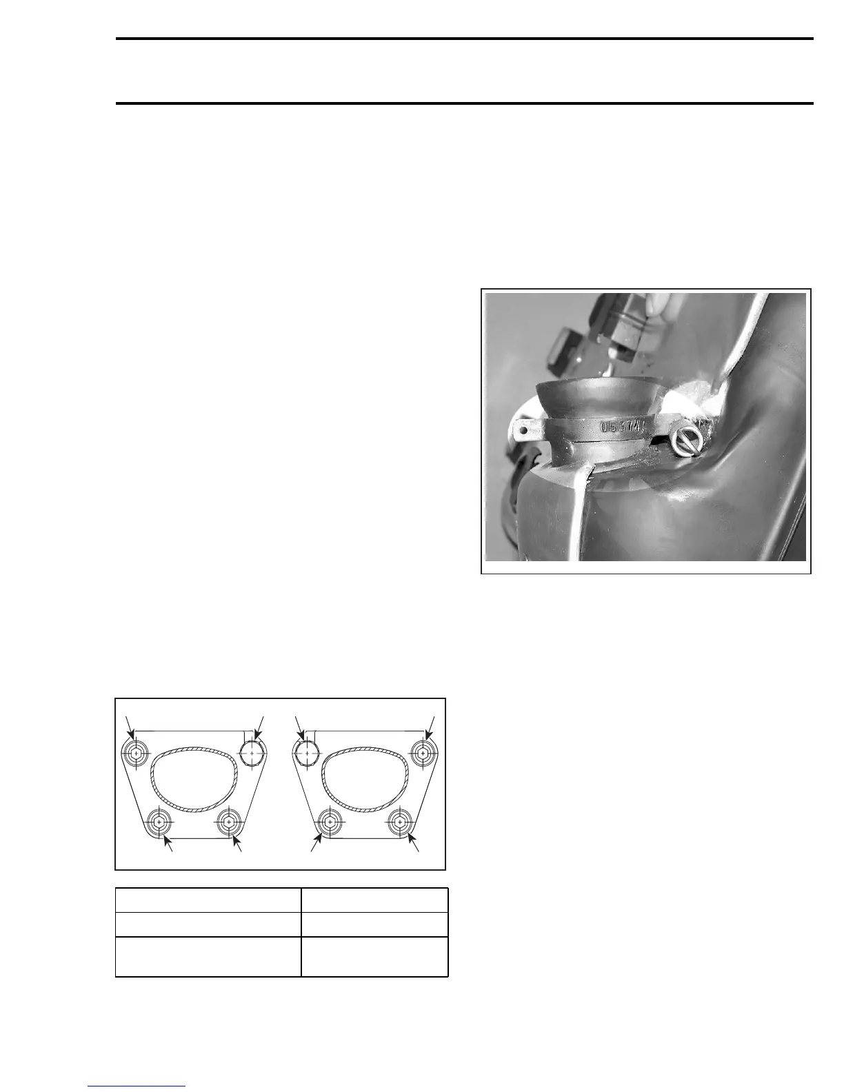
Identification
Each muffler is identified by a number. To use the
proper muffler with the proper vehicle, check the
number on the welded clamp at the end of muffler.
This number depicts the 6 last numbers of BRP
part number.
A33C2MA
TYPICAL
Removal
Remove tuned pipe no. 2.
Disconnect the EGTS (Exhaust Gas Temperature
Sensor) on SDI models.
Remove springs no. 8 retaining the muffler no. 9.
Use exhaust spring installer/remover (P/N 529 035
401).
Remove the muffler.
Inspection
Check the muffler for cracks or other damages.
Refer to the COMPONENT INSPECTION, RE-
PLACEMENT AND ADJUSTMENT section to
verify the EGTS.
Installation
For installation, reverse the removal procedure.
mmr2005-069 55