Section 06 ENGINE MANAGEMENT (SDI)
Subsection 02 (DIAGNOSTIC PROCEDURES)
A33E0YA
2
3
1
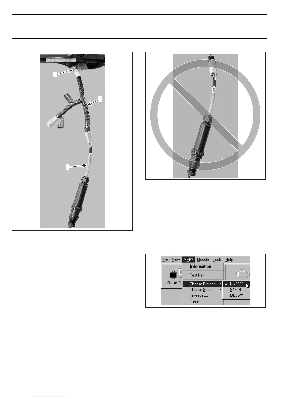
1. Supply harness
2. Vehicle 6-pin connector
3. VCK cable
A33E0ZA
CAUTION: Always use the proper supply har-
ness and cables. Ensure to respect polarity
when connecting cable clips to battery. Match
RED cables together.
Set engine cut-out switch to OFF.
Install the GRAY diagnostic key (P/N 529 035 896)
or any DESS cap onto the vehicle DESS post.
When using the software B.U.D.S., with the SDI:
– ensure that the protocol “KW2000” is properly
selected in “MPI” under “Choose protocol
A33C5LA
– ensure the status bar shows the KW2000 and
thenumber1totheright. Tocommunicatewith
the ECM, number 1 must be displayed.
Number 1 means that one module is connected
with the PC.
246 mmr2005-080