Section 06 ENGINE MANAGEMENT (SDI)
Subsection 03 (COMPONENT INSPECTION, REPLACEMENT AND ADJUSTMENT)
Voltage Test
WARNING
When disconnecting coil from spark plug, al-
ways disconnect coil from main harness first.
Never check for engine ignition spark from
an open coil and/or spark plug in the engine
compartment as spark may cause fuel vapor
to ignite.
Disconnect the plug connector from the ignition
coil and check the voltage supplied by the battery.
3
A32CA5A
2
1
Install tether cord cap on the DESS post and push
the START/RER button momentarily to activate
the ECM.
Check voltage between terminal 2 of ignition
coil connector on the wiring harness and battery
ground.
Battery voltage should be present (approx. 12 V).
If 12 V is NOT read, check continuity between ter-
minal 2 of ignition coil and the corresponding fuse.
Otherwise repair wiring harness.
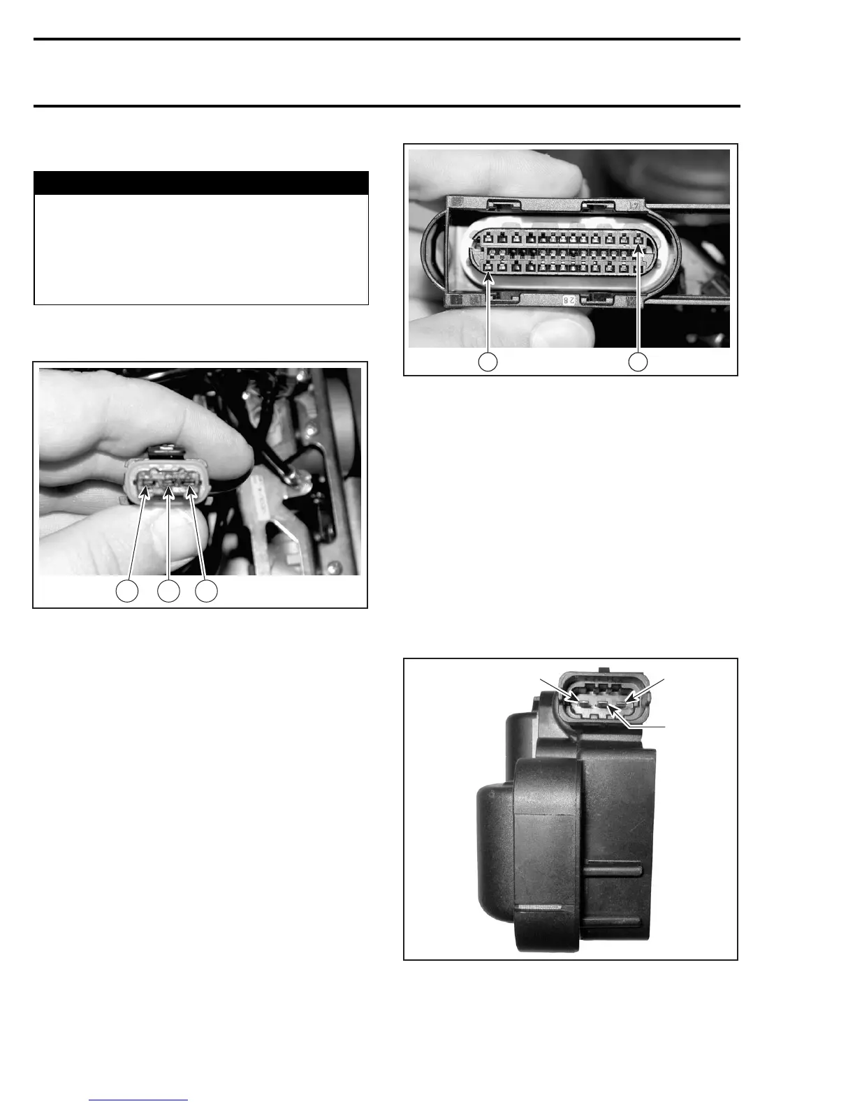
If 12 V is read, disconnect the connector A from
the ECM and check the continuity of appropriate
circuit 41 (cylinder 1) or 1 (cylinder 2) and of ignition
coil connector, pin 3 and pin 1 respectively.
A32C9NC
41
1
ECM CONNECTOR
If wiring harness is defective, repair the connector
or replace the wiring harness between ECM con-
nector and the ignition coil.
If wiring harness is good, test resistance of prima-
ry winding of ignition coil.
Resistance Test
Remove spark plug cables from ignition coil.
Using a multimeter, check the resistance of prima-
ry winding.
NOTE: The secondary winding can not be mea-
sured with an ohmmeter. Try a new double igni-
tion coil if necessary.
A32CCRA
3
2
1
1. Terminal 1a
2. Terminal 15
3. Terminal 1b
274 mmr2005-081