Section 08 DRIVE SYSTEM
Subsection 02 (DRIVE PULLEY)
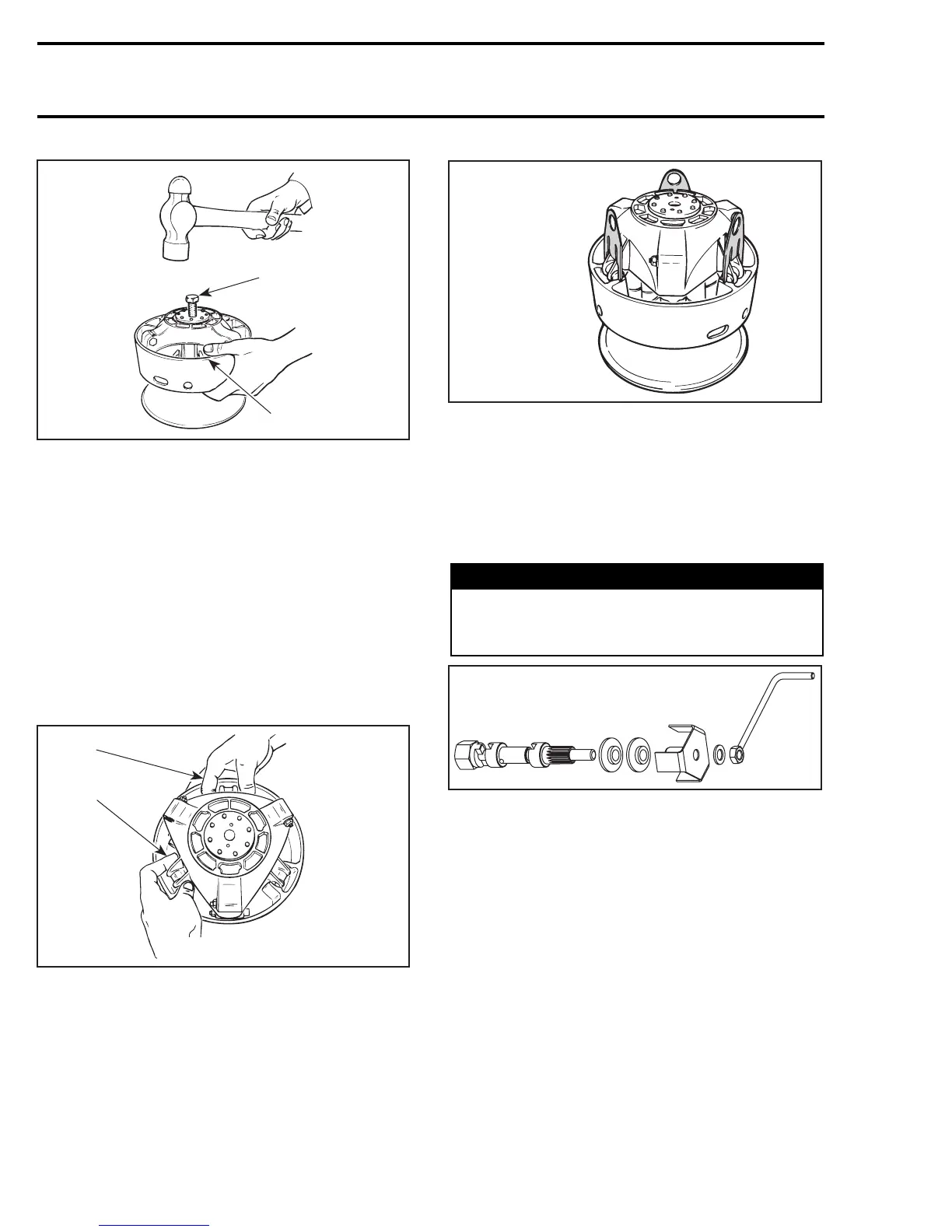
A16D01A
1
2
TYPICAL
1. Puller
2. Holding sliding half
NOTE: No components marking is required before
disassembling this drive pulley since it has factory
mark and arrows as indexing reference.
Slider Shoe and Governor Cup
Carefully lift governor cup no. 7 until slider shoes
no. 9 come at their highest position into guides.
Hold a slider shoe set then carefully lift its housing
and install a slider shoe fork (P/N 529 005 500).
Proceed the same way for other housings lifting
one at a time.
A16D02A
1
2
1. Hold slider shoes
2. Lift one housing at a time
A16B02A
529 005 500
When all slider shoes are held with the forks, re-
move the governor cup.
Spring Cover
To remove the spring cover no. 10, always use the
spring compressor (P/N 529 035 524). The spring
cover is pushed by clutch spring pressure.
WARNING
Clutch spring is very strong. Never attempt
to remove spring cover without the recom-
mended tools.
529 035 524
Install support guide of spring compressor in vice.
330 mmr2005-087