Section 10 STEERING/FRONT SUSPENSION
Subsection 01 (STEERING SYSTEM)
Procedure:
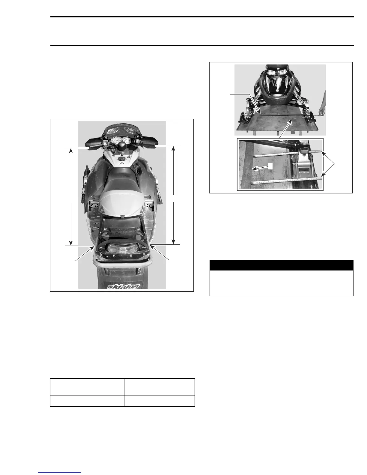
– Position handlebar so that it is in straight ahead
position by measuring from the extremities of
the grips to the rear most edge of the tunnel,
as shown.
NOTE: The reference point must be the same rel-
ative to each side.
A33A2BB
1
2
A A
2
1. Equal distance «A» on each side
2. Same reference point
– Hook a rubber cord in front of skis to keep them
closed and to take all slack from steering mech-
anism.
– Leave the vehicle on the ground on its own
weight.
– Place a straight edge against pre-adjusted track
and measure the distance between front and
rear of ski bridge.
MODEL
TOTAL TOE-OUT
± 1 mm (± 3/64 in)
All REV Series
2(5/64)
NOTE: To reduce tolerance when measuring, set
one ski to proper toe-out (half the total toe-out)
then measure from that ski to the opposite ski.
2
A33G0IA
3
1
TYPICAL
1. Straight edge
2. Rubber cord
3. Measure at rear and front of ski bridge
If adjustment is needed:
– Loosen jam nuts of both tie rods no. 11.
– Turnthetierodtochangeitslength.
– Retighten jam nuts.
WARNING
Never lengthen tie rod so that the external
unengaged threaded portion of ball joint ex-
ceeds 20 mm (25/32 in).
Once ski alignment is done check that ski leg
rests against lower arm or is not more than 2 mm
(5/64 in) from lower arm when the handlebar is
fully turned.
mmr2005-097 445