Fig. 16 Engine Shaft pinion extractor
unscrew the latter. Then withdraw the spring and
cam sleeve, leaving the sprocket and chain in
position. Next, take off the clutch.
REMOVING CLUTCH.
This can be accomplished with the aid of an
extractor (shown in Fig. 30) after removal of the
clutch outer cover, the actuating cap and the
central sleeve nut. The extractor screws into
the thread provided inside the clutch centre.
Now uncouple the chain, the spring link being of
the usual “hairpin” type. Take off the clutch as a
unit and then the cush drive. There now
remains the inner half of the chaincase, which is
held to the crankcase by three bolts, wired
together for locking purposes, and by a nut
attaching the rear chainguard to the case. The
nut can be released easily after the chaincase is
pulled off the crankcase register.
The bolts holding the crankcase to the front and
rear engine plates can now be removed and it is
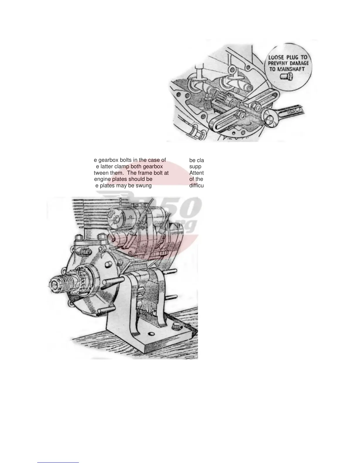
advisable to release the gearbox bolts in the case of
the rear plates, since the latter clamp both gearbox
and crankcase lugs between them. The frame bolt at
the bottom of the front engine plates should be
slackened off so that the plates may be swung
forward, greatly facilitating removal of the engine.
DISMANTLING THE ENGINE
It is advisable before commencing to dismantle the
engine to construct a simple fixture such as that
shown in Fig. 15 on which the engine can be
mounted. Alternatively, a lug on the crankcase may
be clamped in a vice and the crankcase itself
supported on the bench.
Attention may next be given to the crankcase portion
of the engine. Take off the timing cover, and if any
difficulty is experienced in releasing the screws, if will
facilitate matters if a long screwdriver is
used, and the head given a sharp tap with a
mallet. On some models an oil tell-tale is
fitted on the timing cover and this must also
be taken off. It is possible that the jointing
compound on the case between the cover
and crankcase will not allow the cover to be
removed easily and in this event, the lugs on
the end of the cover should be used to tap it
off. Take care not to damage the small
nozzle in the timing cover which feeds oil to
the hollow crankshaft; if it should be refitted
in a bent condition it will foul the mainshaft,
and break off eventually, thus starving the
big end and piston of oil.
REMOVING MAGDYNO PINION
Next, the magdyno pinion should be
removed. Since the pinion fits on to a taper
shaft difficulty may be experienced in
removing it. It is not advisable to attempt to
prise the pinion off with levers, as there is a
grave risk of breaking the timing case, but it
will come off quite simply provided an
extractor to that shewn in Fig. 10 is used.
Note that there is a special oil seal fitted in
the timing case, behind the magneto pinion.
It is only necessary to release the magdyno
strap bolt, when the straps can be swung on
one side, and the magdyno lifted off. The latter is
located by dowels only, and if any shims were fitted
below the magdyno they should be carefully
preserved.
13