After setting, by slackening or tightening the securing
nut (F, Fig 49) prevent further movement by bending
up the tab of the lock washer (E). Refit the dynamo
and pack the gears with high melting point grease.
Secure the drive end cover in position with the gasket
correctly located between the cover and the end of
the magdyno.
Replace the pick-up, first checking that the brush
moves freely and that the cork gasket is free from
cracks.
Refit the earthing brush (Fig 52).
CHARGING (Section B)
DYNAMO TYPE E3HM
B (1) Dynamo Testing in Position
(a) Check that the Dynamo and regulator unit are
wired correctly. The dynamo terminal “D” should be
connected to the regulator unit terminal “D” and
dynamo terminal “F” to the regulator unit terminal “F”.
(b) Remove the cables from the dynamo terminals
“D” and “F” and connect the two terminals with a
short length of wire.
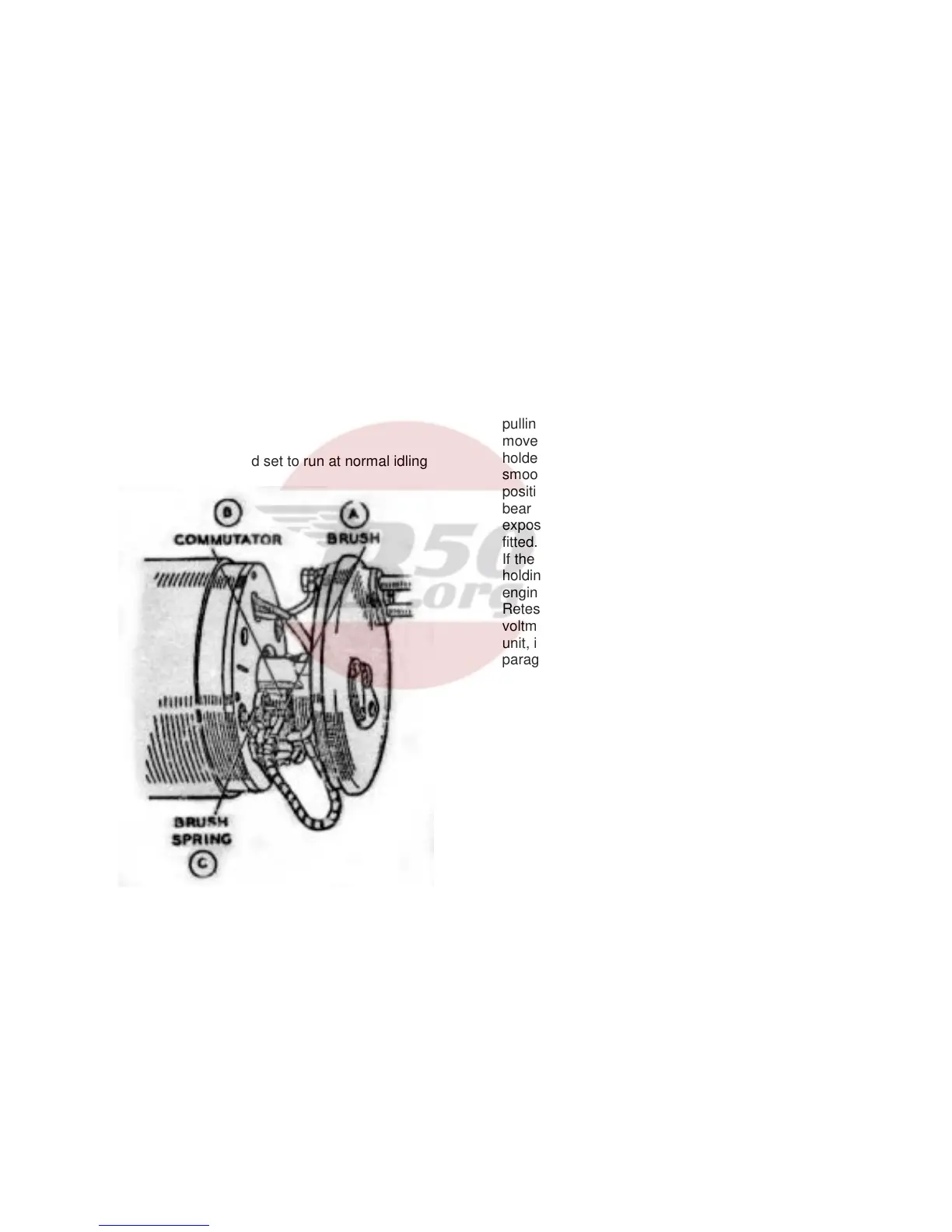
(c) Start the engine and set to run at normal idling
speed.
Fig. 58. Dynamo with cover band removed to
show brush gear.
(d) Connect the positive lead of a moving coil
voltmeter calibrated not less than 1-10 Volts to one of
the dynamo terminals and connect the negative lead
to a good earthing point on the dynamo yoke or
engine.
(e) Gradually increase the engine speed, when the
voltmeter reading should rise rapidly and without
fluctuation. Do not allow the voltmeter reading to rise
above 10 volts. Do not race the engine in an attempt
to increase the voltage. It is sufficient to run the
dynamo up to a speed of 1,000 rpm. If there is no
reading, check the brush gear as described in
paragraph 1 (f). If there is a low reading of
approximately ½ Volt, the field winding may be at
fault. If there is a reading of approximately 1 ½ to 2
Volts, the armature winding may be at fault.
(f) Remove the dynamo cover band and examine the
brushes (A, Fig 58) and commutator (B). Hold back
each of the brush springs (C) and move the brush by
pulling gently on its flexible connector. If the
movement is sluggish, remove the brush from its
holder and ease the sides by lightly polishing on a
smooth file. Always replace brushes in their original
positions. If the brushes are worn so that they do not
bear on the commutator, or if the brush flexible is
exposed on the running face , new brushes must be
fitted.
If the commutator is blackened or dirty, clean it by
holding a petrol moistened cloth against it while the
engine is turned slowly by means of the kickstart.
Retest the dynamo; if there is still no reading on the
voltmeter, there is an internal fault and the complete
unit, if a spare is available, should be replaced – see
paragraph B (2).
(g) If the dynamo is in good order, restore the
original connections to the dynamo. Connect
regulator unit terminal “D” to dynamo terminal “D”
and regulator terminal “F” to dynamo terminal “F”.
Remove the lead from the “D” terminal on the
regulator unit and connect the voltmeter between this
cable and an earthing point on the engine. Run the
cable as before. The reading should be the same as
that measured directly at the dynamo. No reading
indicates a break in the cable to the dynamo. If the
reading is correct, test the regulator unit – see
paragraph B (11), page 41.
B (2) Dynamo To remove and replace.
Take off the connections from the dynamo terminals,
unscrew the hexagon headed nut (A1, Fig 51) from
the driving end cover of the magdyno, slacken the
two screws (B1, Fig 51) securing the band clip and
draw the dynamo out of its mounting.
When replacing, slide the dynamo through the band
clip so that fixing screw (A, Fig 59) passes through its
hole in the end cover and the gears mesh correctly.
Tighten the end nut and the band clip fixing screws
and remake the connections to the dynamo terminals
38.