A (14) Re-assembling.
Wash the bearings in petrol, dry thoroughly and
repack with high melting point grease. Fit ball races
on armature shaft by means of a hand press and use
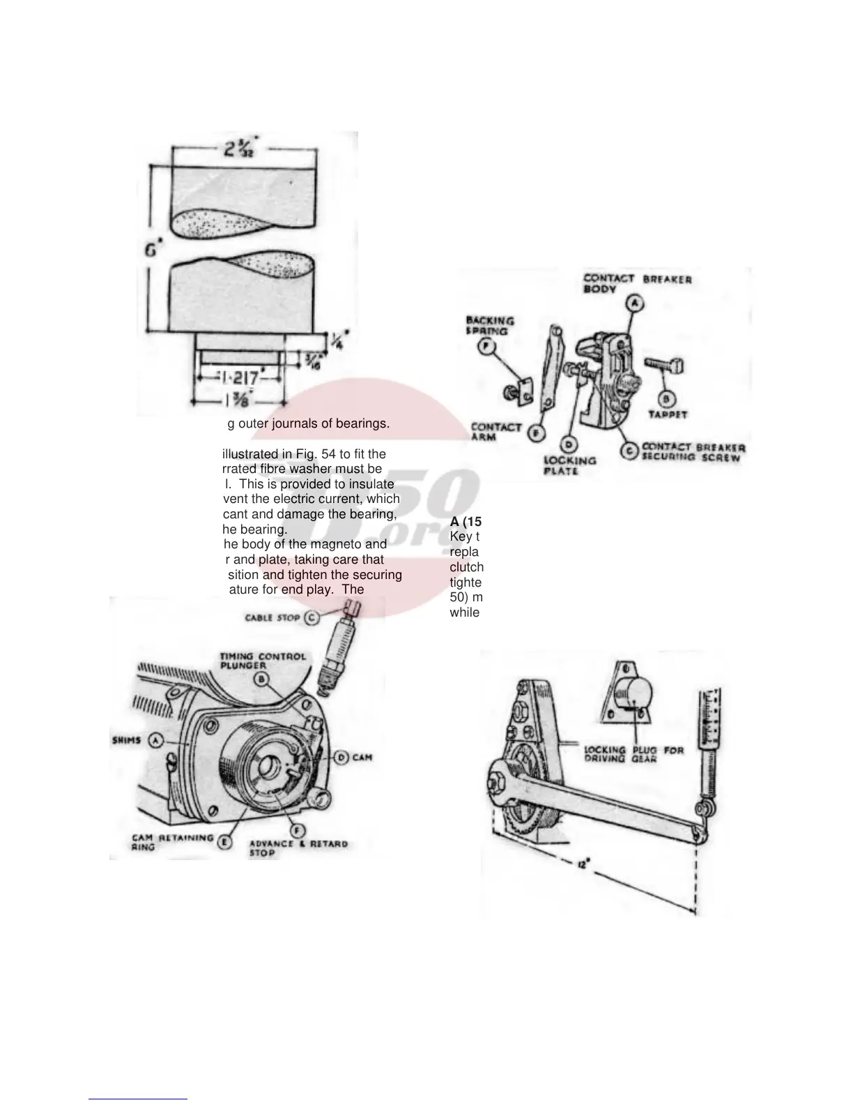
Fig. 54. Tool for fitting outer journals of bearings.
a mandrel of the type illustrated in Fig. 54 to fit the
outer journals. The serrated fibre washer must be
fitted behind the journal. This is provided to insulate
the bearing and so prevent the electric current, which
would destroy the lubricant and damage the bearing,
from passing through the bearing.
Place the armature in the body of the magneto and
refit the contact breaker and plate, taking care that
the end shims are in position and tighten the securing
screws. Check the armature for end play. The
Fig. 55. Magneto contact breaker end showing
fitting of cam, timing control and shims.
armature should revolve freely when turned by hand
but no end play should be felt. Adjust by adding or
removing shims (A, Fig. 55) and spring and secure
by tightening the cable stop (C). Locate the cam (D)
in the contact breaker housing with the timing control
plunger in its correct slot as shown in Fig. 55 and
secure by springing the circlip (E) into its location in
the housing. (Note that the cam is fitted with its flat
side towards the armature).
Fit the contact breaker body (A, Fig. 56) in position
on the location at the end of the shaft after making
sure that the tappet (B) is free and is located
correctly in its guides. Place the contact breaker
securing screw (C) and locking plate (D) in position,
tighten and lock by bending up the tags of the locking
plate.
Refit the spring contact arm (E) with the backing
spring (F) in its correct position i.e., with the bent
portion facing outwards. Check the contact breaker
gap and if necessary adjust to correct setting.
Fig. 56. Contact breaker assembly.
A (15) Re-assembling and Testing Slipping Clutch
Key the gear centre (A, Fig. 49) on to the spindle,
replace the driving gear (B), friction washer (C),
clutch spring (D). locking washer (E) and secure by
tightening the fixing nut (F). The U shaped jig (Fig.
50) must be used to prevent rotation of the shaft
while tightening the nut. After assembling, the setting
of the clutch must be checked. This can easily be
done by locking the driving gear and applying a
Fig. 57. Method of checking clutch setting
steady load on the driving spindle, as shown in Fig.
57. The clutch should slip with a load of 4-10 lbs.
feet, i.e., a 4-10 lb. pull measured out on a spring
balance via a spanner one foot long.
37