RE-ASSEMBLING THE ENGINE
The need for extreme cleanliness cannot be over-emphasised.
Parts should be thoroughly cleaned and all trace of any antirust preparations with which new parts may be
coated must be removed.
All bearing surfaces should be liberally smeared with engine oil when assembling.
FLYWHEELS
If the big end assembly is to be renewed it is as well
to check the weight of the new components
against
those which have been removed. A slight variation in
the weights is inevitable, but provided that the
discrepancy does not exceed 1 ½ oz no further
action need be taken. This tolerance should not be
exceeded since in the first instance the flywheels
have been balanced to suit the original parts, and the
balance may be adversely affected if the weight of
the new components varies considerably from that of
the original ones.
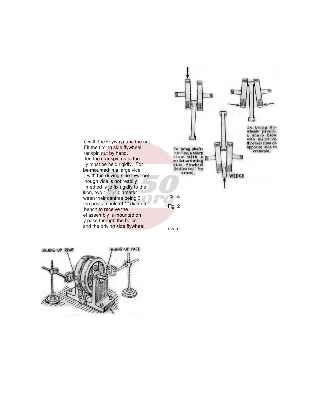
The driving side flywheel should now be fitted to the
crankpin (this is the side with the keyway) and the nut
tightened up by hand. Fit the timing side flywheel
and again tighten the crankpin nut by hand.
In order properly to tighten the crankpin nuts, the
whole flywheel assembly must be held rigidly. For
this purpose, it should be mounted in a large vice
(fitted with lead clamps) with the driving side flywheel
uppermost. If a large enough vice is not readily
available an alternative method is to fix rigidly to the
bench in a vertical position, two 1
1
/
16
” diameter
posts, the distance between their centres being 3
7
/
8
”. Midway between the posts a hole of 1” diameter
should be bored in the bench to receive the
mainshaft. The flywheel assembly is mounted on
these posts so that they pass through the holes
bored in the flywheels and the driving side flywheel
should be uppermost. Tighten the crankpin nut very
firmly, using a tubular extension to the spanner as
when dismantling, and fit the locking plate and screw.
Suitable packing under timing side “vee” block to
compensate for smaller diameter bearing.
Fig. 21. Checking flywheel alignment.
Now turn the assembly over, so that the gearside
flywheel is on top and tighten the crankpin nut lightly.
The grub screw in the end of the crankpin must be
To bring flywheels parallel when sides opposite
Crankpin are converging insert wedges as shown and deal sharp
blow with mallet.
Fig. 22. Method of correcting flywheels out of
alignment. Note that above illustrations are
greatly exaggerated.
riveted over or centre-punched to prevent its
unscrewing. If it unscrews serious damage may
result to the engine. Check that the side clearance of
the connecting rod in the flywheels does not exceed
.012” and is not less than .010”.
The flywheels will now be aligned only very
approximately and further steps must be taken to
ensure that the wheels are aligned as true as
possible. Two of the actual (or similar) bearings to
be used in the engine should be fitted to the
mainshafts and the latter mounted on vee-blocks.
The flywheels must be trued up, both on faces and
rims, for which purpose a dial micrometer is
necessary (Fig. 21), and after the wheels are trued to
within at least .005” tighten the timing side crankpin
nut fully. A mallet or lead hammer applied to the
flywheels will provide a sufficiently heavy blow for
final truing, and will not harm the flywheels (Fig. 22).
The shafts must not be struck. The shafts should be
finally trued to within .002” maximum.
16