bush should be pressed in until it is flush with
the face of the end bracket. Fit the felt ring in
the space between the bearing and the wall
of the bearing housing.
Fig. 65. Removing the ballrace.
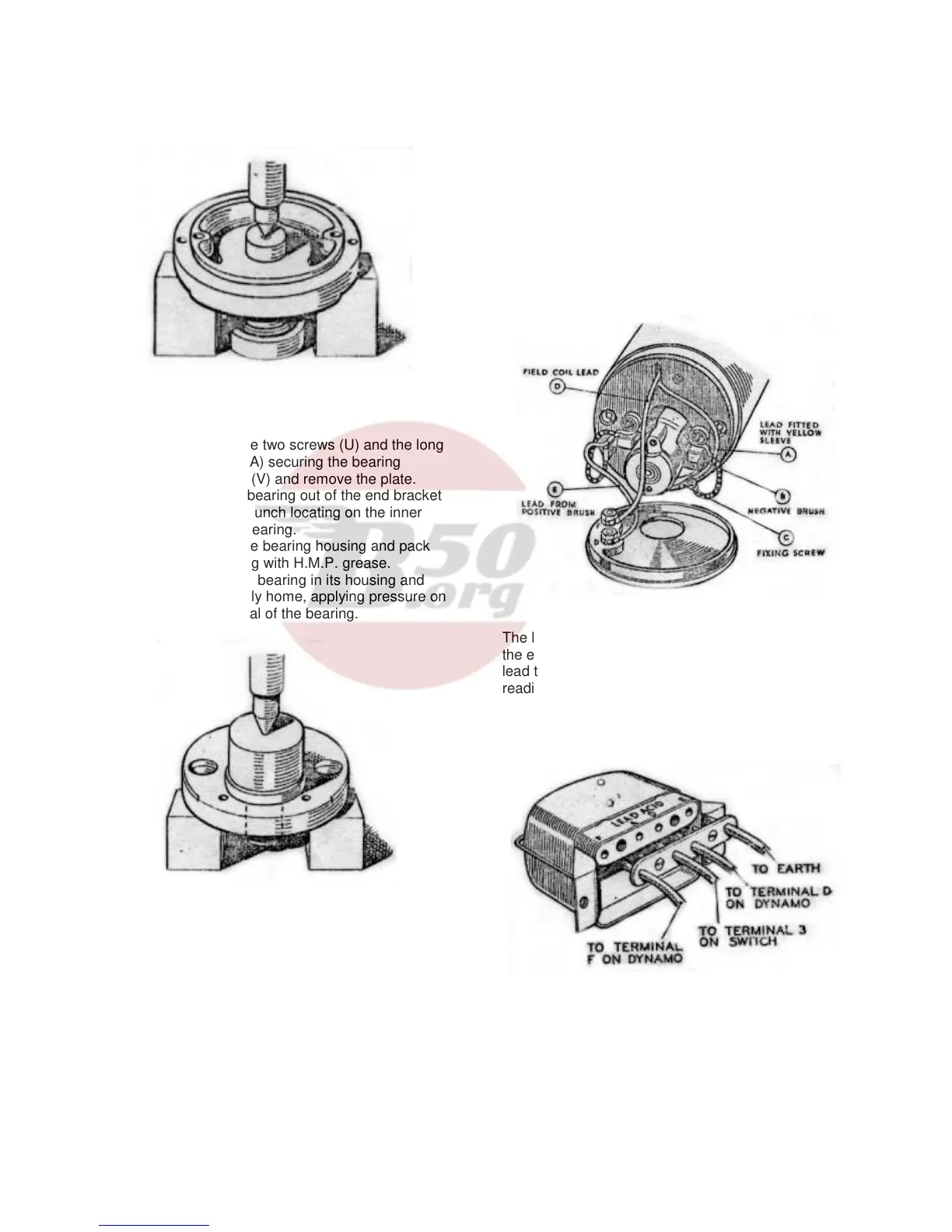
The ball bearing (W, Fig. 59) at the driving end is
replaced as follows:-
(a) Take out the two screws (U) and the long
threaded bolt (A) securing the bearing
retaining plate (V) and remove the plate.
(b) Press the bearing out of the end bracket
using a metal punch locating on the inner
journal of the bearing.
(c) Wipe out the bearing housing and pack
the new bearing with H.M.P. grease.
(d) Position the bearing in its housing and
press it squarely home, applying pressure on
the outer journal of the bearing.
Fig. 66. Fitting Ballrace.
B (9) Dynamo – Re-assembly
In the main, the re-assembly of the dynamo is a
reversal of the operations described in paragraph B
(3), page 39, bearing in mind the following points:-
(a) The field coil lead fitted with the short
length of yellow tubing must be secured
together with eyelet of the negative brush to
the commutator end bracket by means of the
screw provided.
(b) The lead coloured white from the
terminal on the positive brush box must be
connected to terminal “D” on the moulded
end cap.
B (10) Cut-out and Regulator Unit, Type MCR1
This unit houses the dynamo voltage regulator unit
and the cut-out. Both units are accurately set and
the cover should be removed for cleaning and
adjustment only in the event of trouble with the
charging circuit being experienced.
B (11) Regulator – Testing in position.
(a) Before checking the regulator make sure that the
wiring between the regulator and the battery is in
order. To do this, disconnect the wire from the “A”
terminal of the regulator unit and connect
Fig. 67. Internal connections of dynamo.
The lead from the positive terminal of a voltmeter to
the end of the wire. Connect the negative voltmeter
lead to an earthing point on the engine. If a voltmeter
reading is given, the wire is in good order and the
regulator should be examined. If there is no reading
examine the wiring for broken cables or bad
connections.
Fig. 68. Connections to the cut-out and regulator
unit.
(b) Remove the cable from the terminal on the
regulator marked “A”. Connect the positive terminal
of the voltmeter to the “D” terminal on the regulator
and connect the other lead of the voltmeter to an
earthing point on the engine
41