Fig. 25. Assembly of chaincase and footrest.
not be driven on very firmly but just tightly enough to
prevent slip. Check the backlash between this pinion
and the idler. If excessive, the gears will be noisy; if
insufficient, a whining noise will result.
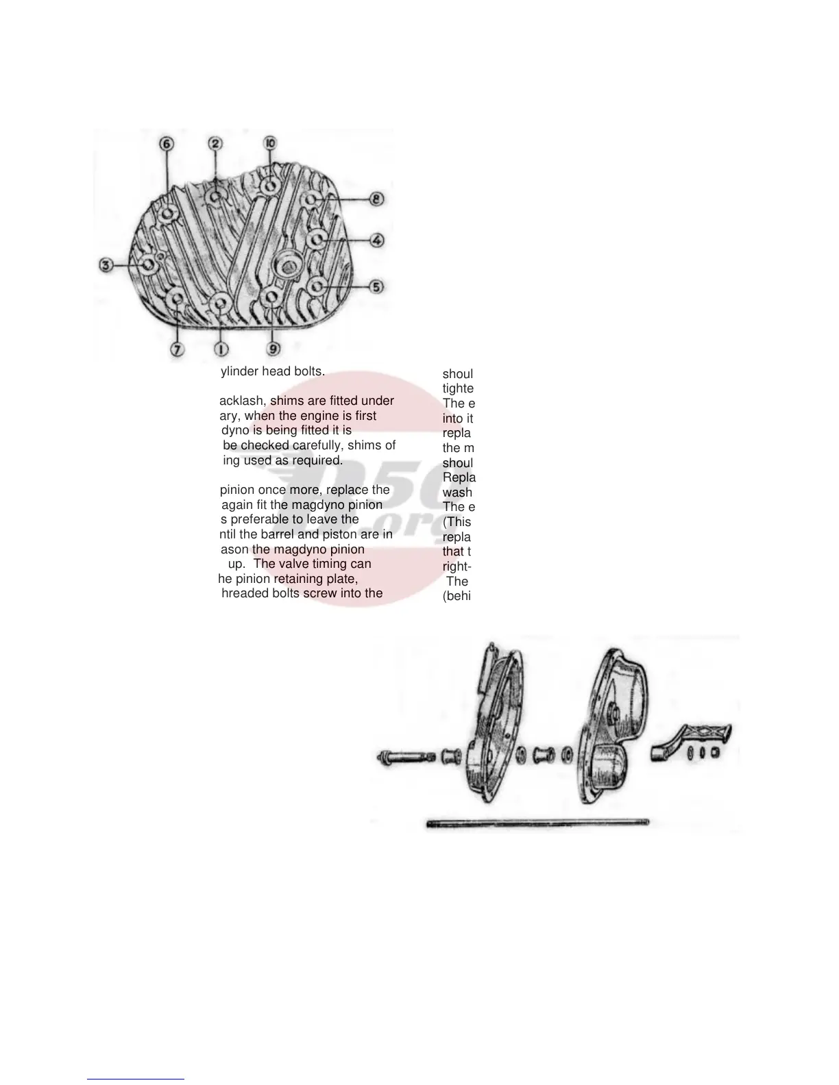
Fig. 24. Cylinder head bolts.
In order to adjust the backlash, shims are fitted under
the magdyno if necessary, when the engine is first
built. If a different magdyno is being fitted it is
essential this backlash be checked carefully, shims of
a different thickness being used as required.
Remove the magdyno pinion once more, replace the
oil sealing washer and again fit the magdyno pinion
loosely in position. It is preferable to leave the
setting of the ignition until the barrel and piston are in
position, and for this reason the magdyno pinion
should not be tightened up. The valve timing can
now be set. Replace the pinion retaining plate,
noting that the coarse threaded bolts screw into the
crankcase bosses and then fit the lockwasher and
nut on the engine mainshaft. Play between the
pinions and the retaining plate should be
.002”/.003”.
ASSEMBLY FROM THIS POINT WILL BE
THE SAME AS AFTER
DECARBONISING.
CYLINDER AND PISTON
The gap between the ends of the rings
should be checked with the ring in the
cylinder. If the gap is excessive new rings
should be fitted with gaps of .008”/.012”.
Replace the piston and gudgeon pin on the
connecting rod and if the original piston is
used make sure that it is the correct way
round (see Page 12). Do not omit the
gudgeon pin circlips and verify that they are properly
fitted.
Set the tappets on their lowest position, fit the paper
washer on the cylinder base and replace the cylinder
barrel on the crankcase. The piston rings may be
compressed quite easily by hand while the barrel is
being replaced.
Tighten the barrel down, not forgetting one nut is
inside the tappet chest. The tappet clearances
should be set very carefully as described on pages 8
and 9.
Next set the ignition timing as described on Page 9.
Note that as the magneto cable is disconnected the
cam will be in the “full retard” position and it must be
held in the “full advance” position.
The resetting of magneto timing will not apply after
decarbonising as there is no necessity to disturb the
timing to remove the cylinder head and barrel.
Replace the timing cover after lightly smearing both
sides of its paper washer with jointing compound,
taking care that the oil hole (Fig. 17) is not
obscured. (This does not apply after
decarbonising). Bolt the cylinder head and gasket in
position, but if the latter shows signs of leakage from
previous use (indicated by black patches) a new one
should be fitted. The cylinder head bolts must be
tightened down in the order shown in Fig. 24.
The exhaust valve lifter body may now be screwed
into its original position. Before the sparking plug is
replaced it should be dismantled and cleaned, or if
the machine has covered a large mileage a new plug
should be used
Replace the tappet cover and lightly smear the
washer with jointing compound before fitting.
The engine is now ready for bolting into the frame
(This does not apply after decarbonising), and after
replacement check that the bolts are really tight, and
that the gearbox bolts have not been forgotten. Refit
right-hand footrest assembly pushing rod fully home.
The near-side footrest sleeve and distance piece
(behind chaincase) should now be placed in position.
Then refit the inner half of the chaincase (first
checking that oil-seal washer is in good condition)
and when the bolts holding it to the crankcase have
been finally tightened, wire them together with a fresh
piece of wire for locking purposes.
The engine shaft cush drive can be replaced by
hand, without the need for special tools to compress
18