Fig. 17 Oil pump spindle locking plunger
The engine shaft nut should be removed and the
plate holding the timing gears in position is detached
by removal of the six fixing bolts, three of which
screw into the crankcase casting and have coarse
threads, while the remaining three screw into the
pinion spindles and have fine threads. All the pinions
can now be withdrawn with the exception of the
engine shaft pinion which may require an extractor.
The latter is shown in Fig. 16, and in order to prevent
damage to the engine mainshaft, a flat headed pin of
suitable dimensions should be inserted in the oil hole,
in the manner illustrated. If the pinions are re-bushed
they should be reamed out to .6255”/.6250” for the
cams and .7505”/.7495” for the idler pinion. The
correct size for the outrigger bearing in the timing
gear plate is .815”/.814”.
Before the oil pump spindle is released it is first
necessary to remove the locking plunger which is
exposed after removal of the timing cover (Fig. 17).
Take care not to lose the loose washer covering the
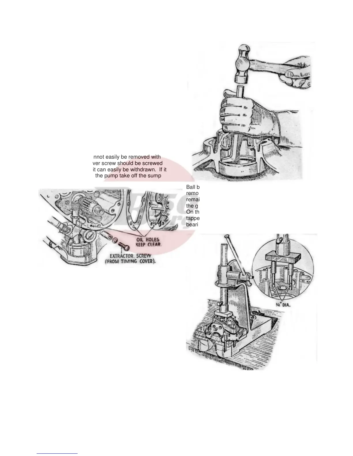
plunger. If the latter cannot easily be removed with
the fingers, a timing cover screw should be screwed
into the plunger, when it can easily be withdrawn. If it
is necessary to remove the pump take off the sump
cover plate, together with the filter and joint washers,
and remove the two bolts holding the pump in
position, thus releasing the pump. These two bolts
are the ones with spring washers under the heads;
the other two bolts hold the pump parts together and
should not be disturbed unless it is strongly
suspected that the pump is giving trouble.
The crankcase is now ready for “splitting”. Release
all the bolts around the crankcase joint face (the
magneto strap hinge pins also act as bolts and the
nut on these must be removed) and draw each half of
the crankcase off the engine mainshaft. Where
single lipped roller bearings have been used in the
engine, the outer race will remain in the crankcase
and if necessary can be pressed out later. It should
be remembered that the outside bearing on the drive
side has its outer race retained in the crankcase by
means of a spring ring which must be removed
before extracting the race.
Ball bearings will usually be left on the shafts after
removal of the crankcase halves, but should they
remain in the crankcase, they may be pressed out of
the gearside in an arbor press as shown in Fig. 19.
On the drive side the inner bearing must first be
tapped out with a punch, projecting through the outer
bearing and, working all round the
Fig. 19. Ballrace extraction (gearside)
14