Fig. 20 Cam pinion spindle extractor.
Bearing to give even extraction (Fig. 18).
These operations will be considerably
helped if the crankcase is first warmed, the
most suitable method being by dipping in
boiling water.
If it is desired to remove the cam pinion
spindles, they can easily be taken out by
means of an extractor (Fig. 20). Do not
remove these spindles unless
absolutely necessary. If the tappets
require renewal, then the cam spindles and
tappet guides must be withdrawn so that
the tappets can be drawn out downwards
into the timing case. The exhaust tappet
requires special treatment, and should not
be replaced by an inlet tappet. The tappet
guides unscrew upwards out of the
crankcase.
The final item is the flywheel assembly. Remove the
locking plates holding the crankpin nuts and take off
the latter. They will require an unusually large
leverage and it may be necessary to add a piece of
tubing of suitable size to the spanner before sufficient
purchase can be obtained.
The crankpin is a taper fit on the flywheels and can
be released by a sharp blow with a mallet.
It is now only necessary to decide which parts require
renewal, and the following points may be of
assistance in making these decisions.
In the event of big-end wear, we do not advise the
fitting of oversize rollers; the whole big end assembly
(consisting of crankpin, rollers and connecting rod),
should be changed. All these components are
carefully matched by the B.S.A. Co., and supplied in
complete sets ready for fitting.
The bore of a cylinder when new is between 3.2295”
and 3.2280” (82mm) and when the bore (measured
at right angles to the gudgeon pin) shows wear to the
extent of .010” or more, the liner should then be
rebored to ½ mm. oversize (3.2487” – 3.2477”) and a
½ mm oversize piston fitted. Subsequently, the liner
may again be rebored, to 1 mm. oversize (3.2684” –
3.2674”) and a 1 mm. oversize piston fitted.
When wear develops after the second rebore, it is
necessary to fit a new cylinder liner. A suitable screw
or hydraulic press giving a pressure of between 5
and 7 tons is necessary – first to press out the old
liner (which must be pressed out from the base of the
cylinder) and then to insert the new liner, which is
pressed in from the top of the cylinder. Owing to the
possibility of the liner “closing-in” during the fitting
process, it must be ground to a finished diameter of
3.229” – 3.228” when in position.
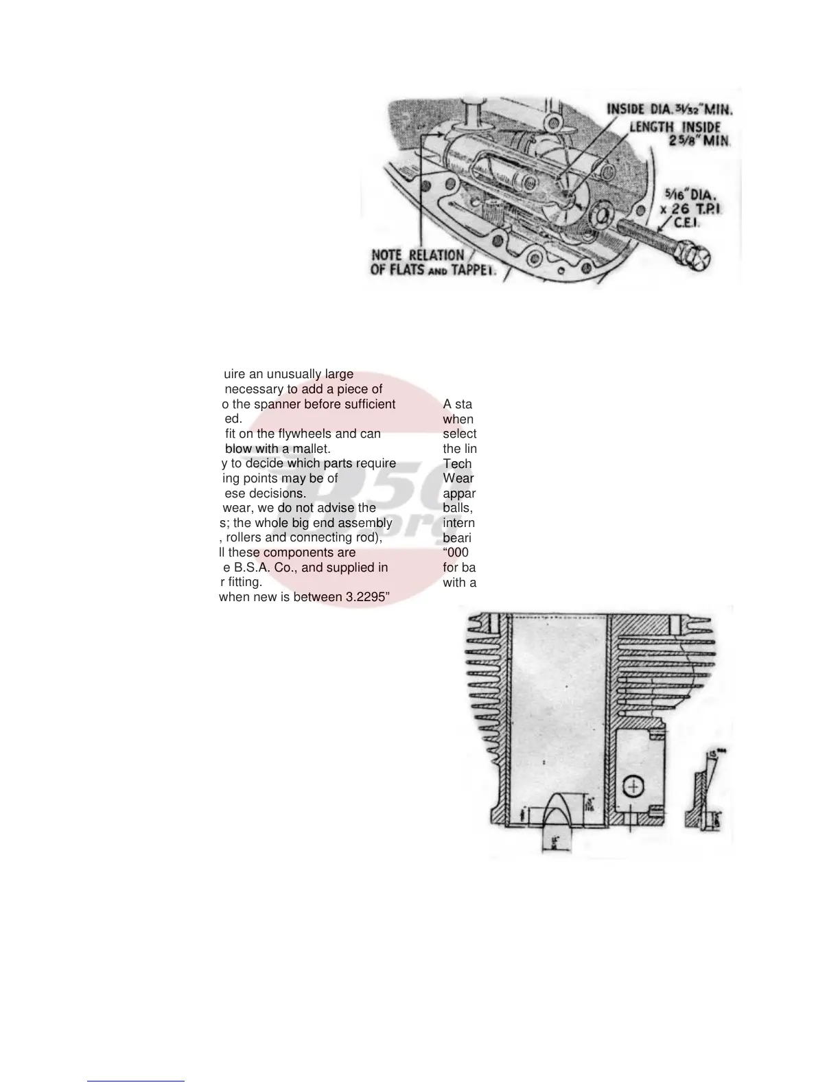
It is also necessary to grind two scoops at the skirt of
the liner at right angles to the gudgeon pin to provide
clearance for the connecting rod (see illustration
below).
A standard piston and rings must of course be fitted
when a new liner is used. The piston should be
selected so that the clearances between the skirt and
the liner fall within the prescribed limits given in
Technical Data (page 2).
Wear in the mainshaft bearings will be readily
apparent and bearings showing signs of damaged
balls, rollers or tracks should be replaced. Special
internal clearances are specified for mainshaft
bearings used on B.S.A. motor cycles, and these are
“000 clearance” for roller bearings and “00 clearance”
for ball bearings. It is not advisable to fit bearings
with any other clearance.
Two scoops diametrically opposite, ground after liner
is pressed in.
15