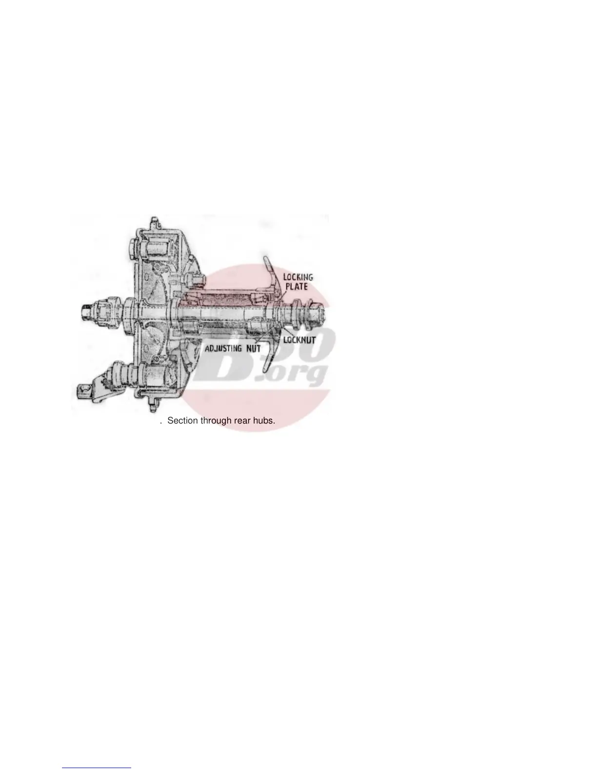
Fig. 39. Section through rear hubs.
ADJUSTMENT, DISMANTLING AND RE-ASSEMBLY
OF HUBS AND BRAKES
REAR HUB (Fig. 39)
The rear wheel is of the quickly detachable type and
the taper roller bearings are contained in the wheel
hub. To remove the rear wheel it is only necessary
to undo the three retaining bolts and withdraw the
spindle from the nearside. The latter is released after
the nut on the offside end is removed. The spindle
does not unscrew; it is a push fit in the hub.
Should it be too tight to be removed by hand, it may
be tapped out from the offside. Remove the distance
piece o the right-hand side and withdraw the hub to
the right from the driving studs. The wheel itself is
now free and can be taken out rearwards after the
detachable portion of the mudguard is removed.
Uncouple the rear chain, the brake cover plate (at its
junction with the torque stay) and the brake rod. The
whole brake drum assembly can now be taken off,
after removal of the locknut on the nearside of the
spindle.
To remove the bearings it is only necessary to take
off the locknut and adjusting nut on the right-hand
side of the hub, when the bearing sleeve may be
drawn out from the opposite side. The outer races of
the bearings are lightly pressed into the hub and will
tap out easily after removal of the dust-cap.
Thoroughly clean the bearings and examine
carefully. If they have been run in too tight a
condition, flats may have been worn on the rollers
and a track formed in the outer race. Check also that
the bearing sleeve and hub spindle have not been
distorted through misuse. If necessary, renew.
The brake drum cover plate can be withdrawn from
the brake drum and it will be seen to carry the brake
shoes together with their fulcrum pin and operating
cam. It is unlikely that these will require attention
although the latter should be checked for freedom of
movement and dismantled and greased if necessary.
To remove the brake shoes, lay drum cover plate flat
on bench (shoes uppermost) and lever shoes
upwards. They can then be drawn over and free of
cam and fulcrum pin. To replace, attach springs and
reverse method of removal. If the cam pads show
excessive wear, new shoes should be fitted,
otherwise if only the brake linings are worn these
alone need be replaced.
If examination of the brake drum shows that the
sprocket teeth have become hook shaped and the
braking drum scored, a new drum must be fitted.
The drum must not be machined to produce a
new braking surface. To do so is only a temporary
cure and further attention would be required
later.
When new linings, or new shoes have been
fitted, the brakes must be centralised after
refitting the wheel. To do this, replace the
brake cover plate, complete with shoes,
fulcrum pin and cam, in the brake drum.
Slacken the fulcrum pin nut, and turn the
cam so as to open the brake shoes in the
normal manner when the fulcrum pin will
move in it’s slot until both shoes are
pressing equally on to the drum. Tighten
the fulcrum pin nut firmly and release the
brake.
RE-ASSEMBLY
After fitting new bearings and bearing
sleeve, together with the adjusting nut, in
position, make certain that there is a trace of
play in the bearings. If they are locked up
so that no play is apparent, rapid wear will
be caused. The adjustment should be such
that the side play at the wheel rim is not more than
1
/
64
Withdraw the wheel spindle and replace the wheel in
position. The wheel bolts must be screwed up
tight and must be kept dead tight at all times.
Slackness will result in elongation of the stud and
dowel holes in the hub flange, necessitating
replacement. The spring washers fitted with these
three bolts have been replaced (commencing with
frame No. WDM20/82773) by chamfered bolt heads
and corresponding spherical seatings in the hub.
Method of tightening is to turn wheel until one of the
three bolts can be seen between mudguard upright
and saddle to hub backstay. Insert bar type box
spanner 69-9038 through hole in hub and engage
head of bolt. Place box spanner 66-9067 over
squared shank of first spanner and tighten bolt as
necessary. A full half turn is possible before
spanners need to be
“ after the locking plate has been replaced and
locknut screwed up tight.
Replace the brake assembly in position and couple
up the rear chain, cover plate and brake rod. Verify
that the brake cam is against its stop and adjust the
chain for tension (see page 20). For this latter
operation, the wheel spindle must be replaced
(without the hub being in position)