REMOVAL AND DISMANTLING OF FRONT
FORKS AND STEERING HEAD
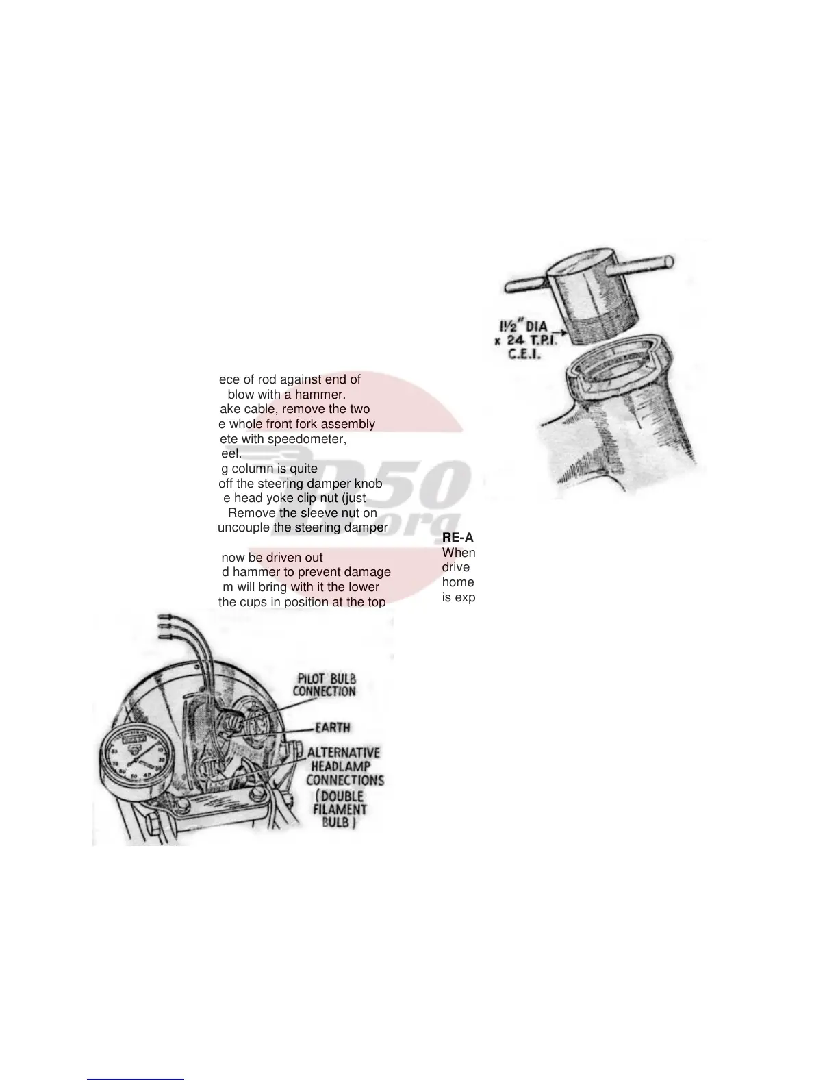
There is no necessity to disturb the electrical system
as a whole, when removing the forks. The
instrument panel on the back of the headlamp is
retained by three screws, and if these are removed,
the panel is released and the wiring can be
withdrawn through the aperture after releasing the
four connections (see Fig. 41). Place a box under
the engine so that the front wheel is clear of the
ground.
Remove the nut from the fork spring top scroll, then
remove both top fork links and prise scroll
downwards until the bolt is free from the headlug.
Headlamp wiring should now be drawn out at the
side of the forks.
To take off the fork spring it is only necessary to
unwind the spring from its bottom scroll. If difficulty is
experienced place a piece of rod against end of
spring and give a sharp blow with a hammer.
Disconnect the front brake cable, remove the two
lower fork links, and the whole front fork assembly
can be taken off complete with speedometer,
headlamp and front wheel.
Dismantling the steering column is quite
straightforward. Take off the steering damper knob
(if fitted) and slacken the head yoke clip nut (just
below the handlebars). Remove the sleeve nut on
top of the column and uncouple the steering damper
plates at the frame lug.
The steering stem can now be driven out
(downwards) with a lead hammer to prevent damage
to the threads. The stem will bring with it the lower
ballrace cone, leaving the cups in position at the top
Fig. 41. Headlamp connections.
and bottom of the steering head. A simple extractor
shown in Fig. 42 is used for the removal of these
cups. They are threaded to take the extractor, which
should be screwed well home, since it engages with
a few threads only. A bar is then inserted from the
opposite end of the head lug, and the extractor and
ballrace driven out together.
If the balance cups and cones are pitted, to even a
slight degree, they must be replaced, otherwise the
steering will be uncomfortable. Note that the pitting
is invariably due to “hammering” of the balls in their
tracks, due to slack adjustment in the first place.
Fig. 42. Steering head ballrace extractor.
RE-ASSEMBLY
When fitting new ballrace cups make sure they are
driven in squarely and that they are pressed well
home. Replace the steering stem and if any difficulty
is experienced in making the balls (of which there are
20 top and 20 bottom – all ¼ “) stay in position, the
tracks should be heavily smeared with grease.
Refit the dust cover and steering head yoke, followed
by the top sleeve nut. The latter may now be
tightened, until there is no trace of play in the head.
On the other hand, do not tighten excessively.
Replace the steering damper rod, complete with
plates, from below and tighten the damper plate
securely to the frame. The lower end of the steering
damper rod is slotted to take the fork link bolt, and
care must be taken to see that the rod is fitted so that
the link bolt can slide through.
The fork spring should be carefully inspected. If it is
suspected as having been weak through prolonged
use over bad roads, or shows signs of collapse, a
new one should be fitted. Attach the spring to its
bottom scroll, and replace the bottom two fork links
loosely in position. Refit the top scroll in position,
draw the wiring to the headlamp forward to it’s
normal position, and assemble the top fork links.
Adjustment of the links should be such that there is
no side play present. The headlamp connections are
shown in Fig. 41.