Undercut the mica insulation between the segments
to a depth of 1/32” (fig. 61) with a hacksaw blade
ground down until it is only slightly thicker than the
mica.
Fig. 61. Method of undercutting mica.
B (6) Dynamo – Field Coil
(a) Test the field coil by connecting it in series with a
six volt battery and a six volt, three watt bulb. If the
field coil is satisfactory, the bulb will light up, but its
brilliance will be somewhat less than when connected
direct to the battery. Failure of the bulb to light
indicates an open circuit in the field winding, while if
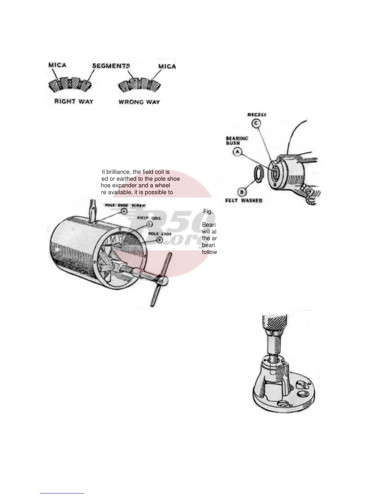
the bulb lights up will full brilliance, the field coil is
probably either shortened or earthed to the pole shoe
or dynamo yoke. If a shoe expander and a wheel
operated screwdriver are available, it is possible to
Fig. 62. Pole shoe and field coil assembly.
replace the field coil. A pole shoe expander is
necessary to ensure there will not be any airgap
between the pole shoe and the inner face of the
yoke.
(b) Replace the field coils as follows:-
(c) Unscrew the pole shoe retaining screw (A, Fig.
62) by means of the wheel operated screwdriver.
(d) Draw the pole shoe (B) and field coil (C) out of the
yoke and lift off the coil.
(e) Fit the new field coil over the pole shoe and place
it in position inside the yoke. Take care to ensure
that the taping of the field coil is not trapped between
the pole shoe and the yoke.
(f) Locate the pole shoe and field coil by lightly
tightening the fixing screw. Insert the pole shoe
expander, open it to its fullest extent and tighten the
screw. Remove the expander and give the screw a
final tightening with the wheel operated screwdriver.
Caulk the screw to lock it in position.
Dynamo - Armature
The testing of the armature winding requires the use
of a volt-drop test or a growler. If these are not
available, the armature should be checked by
substitution. No attempt should be made to machine
the armature core or to true a distorted armature
shaft.
B (8) Dynamo – Bearings.
A ball bearing is fitted at the driving end and a plain
porous bronze bearing bush at the commutator end.
Fig. 63. Commutator end bracket with bearing bush.
Bearings which are worn to such an extent that they
will allow approximately .015” total side movement of
the armature shaft must be replaced. To replace the
bearing bush at the commutator end, proceed as
follows:-
(a) Press the bearing bush (A, Fig. 63) out of
the commutator end bracket and remove the
felt ring (B).
(b) Press the new bearing bush into the end
bracket using a shouldered mandrel of the
same diameter as the shaft which is to fit in
the bearing. Note: Before fitting the new
bearing bush it should
Fig. 64 Fitting bearing bush using a shouldered
mandrel.
Be allowed to stand for 24 hours immersed
for about 7/8ths of its length in thin engine
oil. The
40