REMOVING, DISMANTLING AND RE-ASSEMBLY OF
THE GEARBOX AND GEAR CHANGE
REMOVAL
Instructions as to the procedure to be adopted for
removal of the chaincase and clutch are contained in
the Chapter on “Dismantling and Re-assembly of the
Clutch.” In this case, however, there is no need to
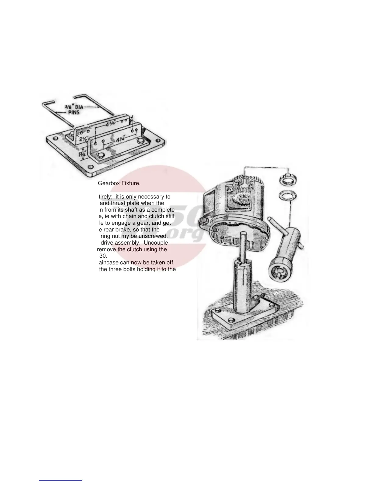
Fig. 33. Gearbox Fixture.
dismantle the clutch entirely; it is only necessary to
take off the cover plate and thrust plate when the
clutch may be withdrawn from its shaft as a complete
unit. Before this is done, ie with chain and clutch still
in position, it is advisable to engage a gear, and get
an assistant to apply the rear brake, so that the
engine shaft cush drive ring nut my be unscrewed,
thus releasing the cush drive assembly. Uncouple
the primary chain and remove the clutch using the
extractor shown in Fig. 30.
The inner half of the chaincase can now be taken off.
Note that in addition to the three bolts holding it to the
crankcase, there is a nut attaching the rear
chainguard to the chaincase and this must also be
removed. Access to the nut will be made much
easier if the three crankcase bolts are unscrewed first
and the chaincase pulled off the crankcase register.
The oil tank breather pipe is next to be removed and
this is only a matter of releasing the clip bolts.
Turning now to the right-hand side of the machine,
first take off the footrest, then uncouple the clutch
cable from its operating arm and unscrew the cable
adjuster from the gearbox.
In order that the bolts which hold the gearbox to the
yoke plates may be removed it is necessary to take
off the exhaust pipe and silencer.
The box itself can be prised upwards out of the yoke
plates. If the latter grip the gearbox lugs too tightly
for this to e carried out easily, slacken the bolts and
studs which clamp the yoke plates to the crankcase.
No difficulty should then be experienced in removing
the gearbox.
DISMANTLING THE GEARBOX
It will greatly help work on the gearbox I it is held in a
simple fixture such as that illustrated in Fig. 33. The
device can be made from suitable pieces of angle
iron, spaced to suit the gearbox lugs. If it is not
possible to make the fixture, gearbox can be held in a
vice.
Commence dismantling by taking off the rectangular
inspection cover and follow this with kickstarter
crank. The latter if fixed by means of a cycle type
cotter. The foot change pedal is held in position by
means of a pinch bolt which must be slackened off
before the pedal can be removed. Behind this pedal
are two circlips, the larger one being removed,
followed by the gear indicator disc. Leave the small
circlip in position for the time being.
Fig. 34. Pinion sleeve removal tool.
The gearbox outer cover is now ready for removal. It
is held on seven cheese head screw and, on the face
behind the gear change mechanism, by three bolts
and on nut. When the outer cover is taken off, it will
contain the kickstarter quadrant and spring, but these
need not be disturbed unless obviously requiring
attention.
23