LIGHTING AND ACCESSORIES (Section C)
C (1) Headlamp, Type DU42
The main bulb should be 6 volt 24 watt. S.B.C.
double contact type. The pilot bulb should be 6 volt
24 watt. S.B.C. centre contact type.
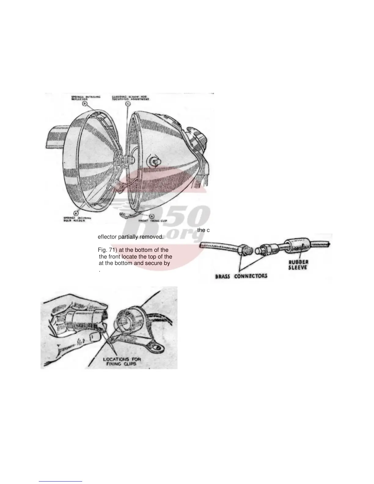
Removing Lamp Front and Reflector.
(a) To remove the lamp front and reflector press
Fig. 71 Headlamp – Reflector partially removed.
back the fixing clip (A, Fig. 71) at the bottom of the
lamp. When replacing the front locate the top of the
rim first, then press on at the bottom and secure by
means of the fixing clip.
To remove bulb holder, press back the securing
springs (B).
Fig. 72
Setting and Focussing
(b) The lamp must be set to ensure that the beam is
projected below the horizontal.
To obtain the best driving light the bulb should be
correctly focussed in the reflector. The mask fitted to
the headlamp is calibrated on the basis that a parallel
beam is projected from the reflector; this achieved by
focussing with the mask removed, until the smallest
circle of light is obtained. Adjust by slackening the
screw in the clamping band and sliding the bulb
holder backwards or forwards.
Tighten the screw after making the adjustment.
The reflector can be withdrawn from the lamp front
when the spring clips are sprung from their locations
inside the front rim.
Cleaning
(c) Care must be taken when handling the
reflector to prevent it from becoming
finger-marked. It can, however, be
cleaned by polishing with a clean chamois
leather. Metal polishes must not be used.
NOTE: The second filament of the main
bulb is for use as a spare in an
emergency. To bring it into service,
remove the bulb, turn it through 180
o
and
refit. Replace the bulb at the first
opportunity.
C (2) Tail Lamp, Type L-WD-MCT1
The bulb should be 6 volt, 3 watt. S.B.C.
centre contact.
To remove the cover carrying the red
glass, twist and pull away from base.
When replacing, position the locations in
the cover over the spring and push home.
Fig. 73. Battery connector.
C (3) Cables.
Before making any alterations to the wiring or
removing the switch from the headlamp, disconnect
the positive lead at the battery to avoid the danger of
short circuits. The lead, about one foot long, from the
positive battery terminal is connected to the lead from
the switch by means of a brass connector, shown in
Fig. 73. The connector is insulated by a rubber
sleeve, which must be pushed back to allow the
connector to be unscrewed. Do not allow the brass
connector to touch any metal part of the engine, as
this will short circuit the battery. When connecting up
again, pull the rubber sleeve over the connector.
C (4) Lighting Switch, Type RS39.
All leads to the headlamp are taken direct to the
switch which together with the ammeter is
incorporated in a small panel (see Fig. 70). The
44