A (10) Removal from engine
Before the magdyno can be removed from the
engine, it is first necessary to take off the timing
cover. With this removed, the magdyno pinion must
next be withdrawn from the shaft by means of the
extractor shown in Fig. 10. There is a special oil seal
washer fitted behind the pinion – see that this is not
lost. Now release the straps holding the magdyno on
its platform, and the whole instrument can be lifted
off.
Retain any shims which may have been fitted under
the base and replace when refitting magdyno.
A (11) Magneto dismantling.
Remove the dynamo (E, Fig. 51) and take off the
driving end cover (F) by unscrewing the four
countersunk head screws. To dismantle the slipping
clutch it will be necessary to use a jig (Fig. 50) to hold
the larger gear whilst the securing nut is being
undone. This consists simply of a length of ¼ “
diameter mild steel rod bent to a flat U, the ends
being cut short with their centres 3
3
/
16
” apart, so that
one can be slipped in the hole in the wheel while the
other is engaged with the hole in the top of the
casting through which the dynamo securing stud
usually goes. The
7
/
16
” box spanner can then be
used on the securing nut (G, Fig. 51) which unscrews
in the normal left-hand direction. Note that the tab of
the locking washer (H) must be bent back first.
Remove the locking washer (H), clutch spring (I),
friction washer (J), driving gear (K) and gear centre
(L).
A (12) Magneto Armature – Removing.
Take off the contact breaker cover (M), remove the
spring arm (N) carrying the contact, unscrew the bolt
(O) securing the contact breaker (P) and draw the
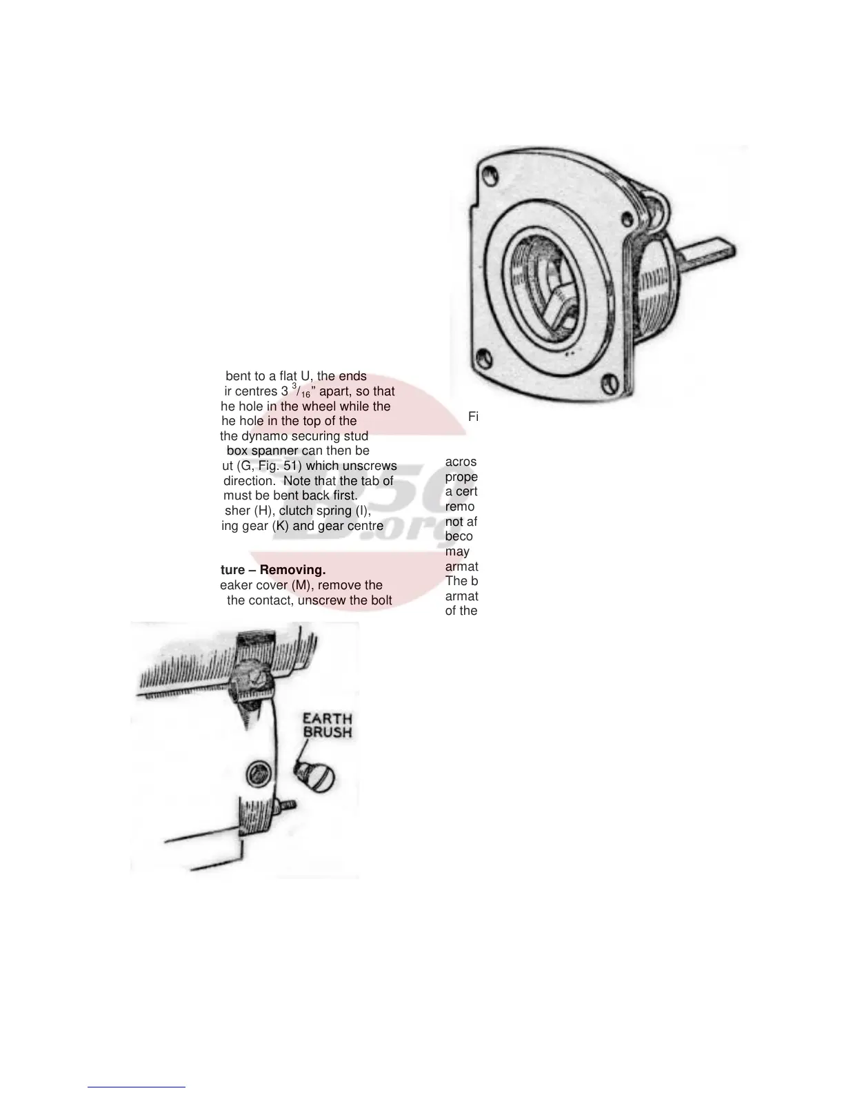
Fig. 52. Magneto earthing brush.
contact breaker off the shaft. Spring the wire ring
(Q), securing the cam (R), out of its location in the
contact breaker housing and remove the cam.
Unscrew the cable stop (S) of the timing control and
remove the control plunger (T). Remove the pick-up
holder and the small earthing brush (Fig. 52) which
will be found on the side of the magdyno. Unscrew
the screws (U, Fig. 51), earthing terminal (V), and
pillar (W) from the contact breaker end plate (X) and
remove the plate from the magdyno, together with
shims (Y). The armature (Z) can then be drawn out
of the machine. There is no need to put a keeper
Fig. 53. Method of removing outer journals of
bearings.
across the magnet as it retains its magnetic
properties more or less indefinitely. Although it loses
a certain immaterial amount of power in the first
removal of the armature, subsequent removals do
not affect it. Do not allow the magneto body to
become in close contact with any iron filings as they
may become attracted to the magnet and cause the
armature to bind.
The ballraces can be removed from the magneto
armature shaft by means of an extractor, while a tool
of the type shown should be used to remove the
outer journals (Fig. 53).
A (13) Magneto Armature Testing.
If test apparatus is not available, a rough check of the
armature windings can be made by means of a two
volt battery (a tapping across one cell of the motor
cycle battery), and an ammeter. Screw the contact
breaker retaining screw (O, Fig. 51) into the end of
the armature shaft. Connect one terminal of the
battery, with the ammeter in series, to the screw.
Connect the other battery terminal to the metal body
of the armature. The ammeter will then record the
current taken by the primary winding – this should be
approximately four amperes. To check the
secondary winding of the armature, wrap the bared
end of a length of H.T. cable round the brass insert of
the slip ring and hold the other about one-eighth from
the armature core. If the lead from the battery which
was connected to the core is then flashed quickly on
and off the core, a spark should occur between the
H.T. cable and the core.
No spark at these points indicates a fault either in the
armature windings or in the condenser and a
replacement armature must be fitted.
36