Fig. 75. Headlamp, type DU42 with reflector partially
removed.
panel can be removed when the three fixing screws
are withdrawn. The ends of all the cables are
identified by means of coloured sleevings. The
colour scheme and the diagram of connections are
shown in the wiring diagram. When making
connections to the switch, bare the end of the cable
for about 3/8”, twist the wire strands together and
turn back about 1/8” so as to form a small ball.
Remove the grub screw from the appropriate terminal
and insert the wire so that the ball fits in the terminal
post. Now replace and tighten the grub screw; this
will compress the ball to make a good electrical
connection.
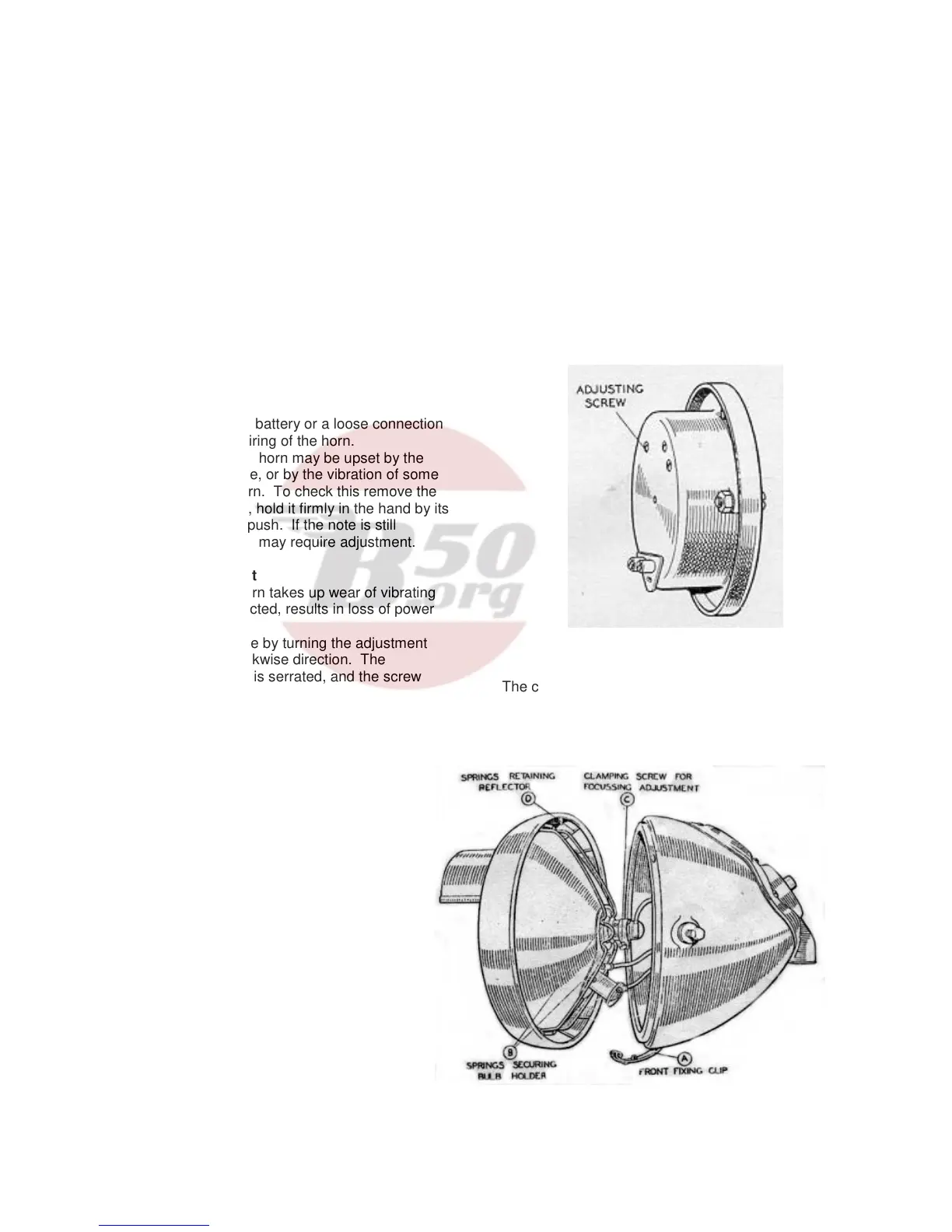
C (5) Horn, Type HF1235
Electric horns are adjusted to give their best
performance before leaving the works and will give a
long period of service without any attention. If the
horn becomes uncertain in action or does not vibrate,
it has not necessarily broken down. The trouble may
be due to a discharged battery or a loose connection
or short circuit in the wiring of the horn.
The performance of the horn may be upset by the
fixing bolt working loose, or by the vibration of some
part adjacent to the horn. To check this remove the
horn from its mounting, hold it firmly in the hand by its
bracket and press the push. If the note is still
unsatisfactory, the horn may require adjustment.
Method of Adjustment
The adjustment of a horn takes up wear of vibrating
parts which if not corrected, results in loss of power
or roughness of tone.
The adjustment is made by turning the adjustment
screw, usually in a clockwise direction. The
underside of the screw is serrated, and the screw
must not be turned for more than two or three
notches before retesting. If the adjustment screw is
turned too far in a clockwise direction, a point will
occur at which the armature pulls in but does not
separate the contacts.
When testing do not continue to operate the push if
the horn does not sound. If when the push is
operated, the horn does not take any current
(indicated by an ammeter connected in series with
the horn), it is possible that the horn has been
adjusted so that its contact breaker is permanently
open.
After adjusting, note the current consumption. A horn
may give a good note, yet be out of adjustment and
taking an excessive current. When adjusting, do not
attempt to unscrew the nut securing the tone disc or
any other screw in the horn.
Fig. 71. Horn showing adjusting screw.
The current, when the horn is adjusted to give its
best performance must not exceed 4-5 amperes.
---------------------------
C (6) Headlamp, Type DU 42. Fitted to
later models.
The headlamp incorporates the main bulb (6
volt 24 watt S.B.C. double contact, double
filament type) and the pilot bulb (6 volt 3 watt
S.B.C. centre contact type).
It differs from the type described in Section C
(1), page 44, in that the ammeter is omitted
and the main lighting switch is removed from
the lamp and is mounted on a separate
bracket. The lamp is fitted with a push
operated switch by means of which the rider
can change from the main bulb to the pilot
bulb or vice versa.
The method of removing the front and reflector
and of setting the focussing remains as
described in Section C (1), page 44.
45