Change-over Switch
A single lead connects the main lighting switch to the
change-over switch and two cables connect the
change-over switch to the main and pilot bulb
holders. To remove the switch proceed as follows:
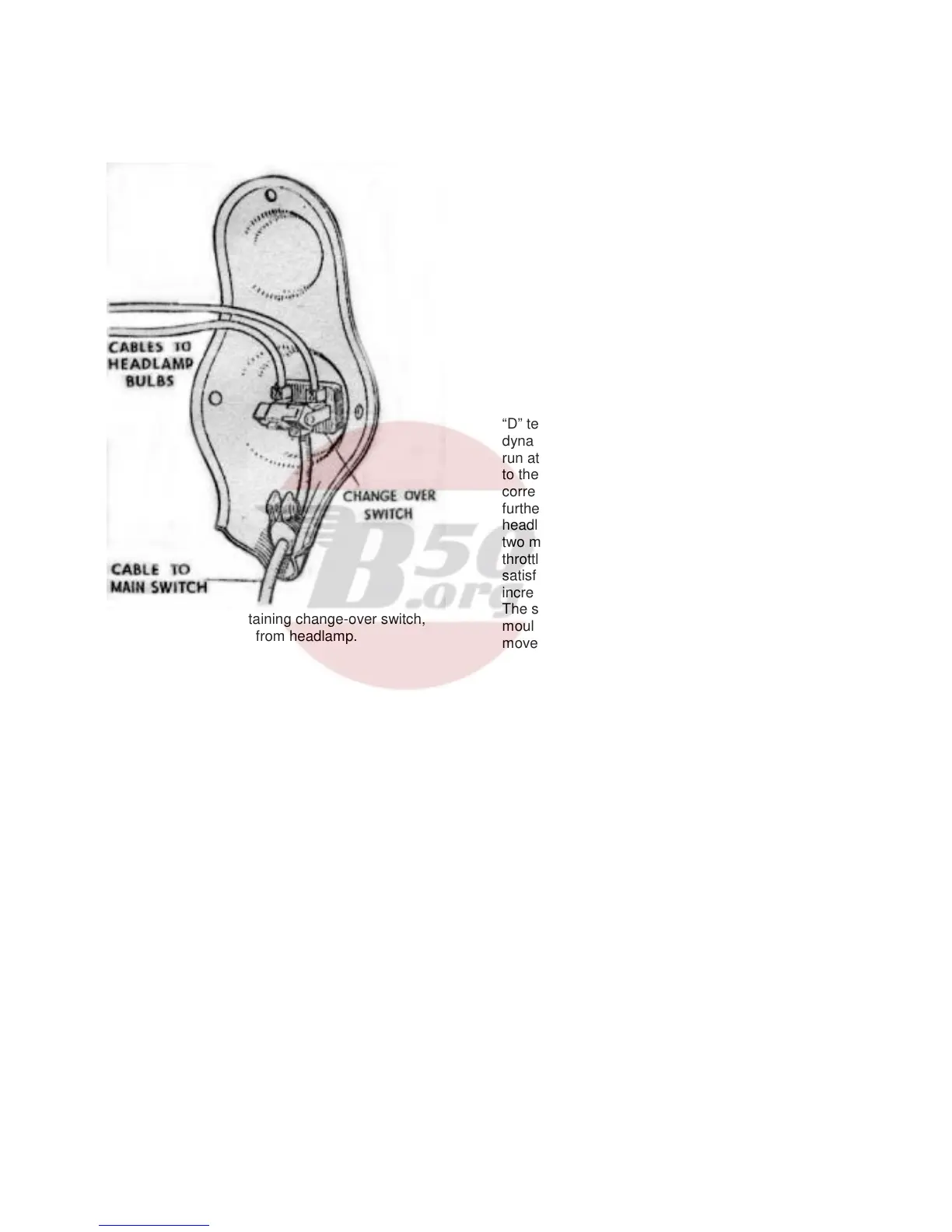
Fig. 76. Panel containing change-over switch,
removed from headlamp.
Take out the three screws securing the panel plate
fitted at the back of the lamp and withdraw the panel
(Fig. 76). Slacken the three screws in the switch
terminals and lift out the cables. Hold the switch
body, unscrew the bezel ring on the outside of the
switch and withdraw the switch, connect the cable
fitted with the blue sleeving to the single terminal on
the one side of the switch plate and connect the two
cables from the bulb holders to the other two
terminals.
Main Lighting Switch
The switch has four positions as follows:-
TEST
OFF
T. Tail lamp on.
H. Headlamp and tail lamp on.
The “Test” position is provided to enable the rider to
check that the dynamo is functioning correctly. In
this position the tail lamp is connected directly to the
“D” terminal on the regulator unit. To check the
dynamo performance, start the engine and allow it to
run at a fairly fast idling speed and move the switch
to the “Test” position. If the dynamo is operating
correctly the tail lamp should light up brightly. As a
further check of the charging system, switch on the
headlamp with the engine stopped and after about
two minutes, start the engine and partly open the
throttle. An indication that the charging system is
satisfactory is given if the brightness of the lamp
increases.
The switch terminals are accessible when the
moulded cover, which is secured by three nuts, is
moved back along the cables.
46