24
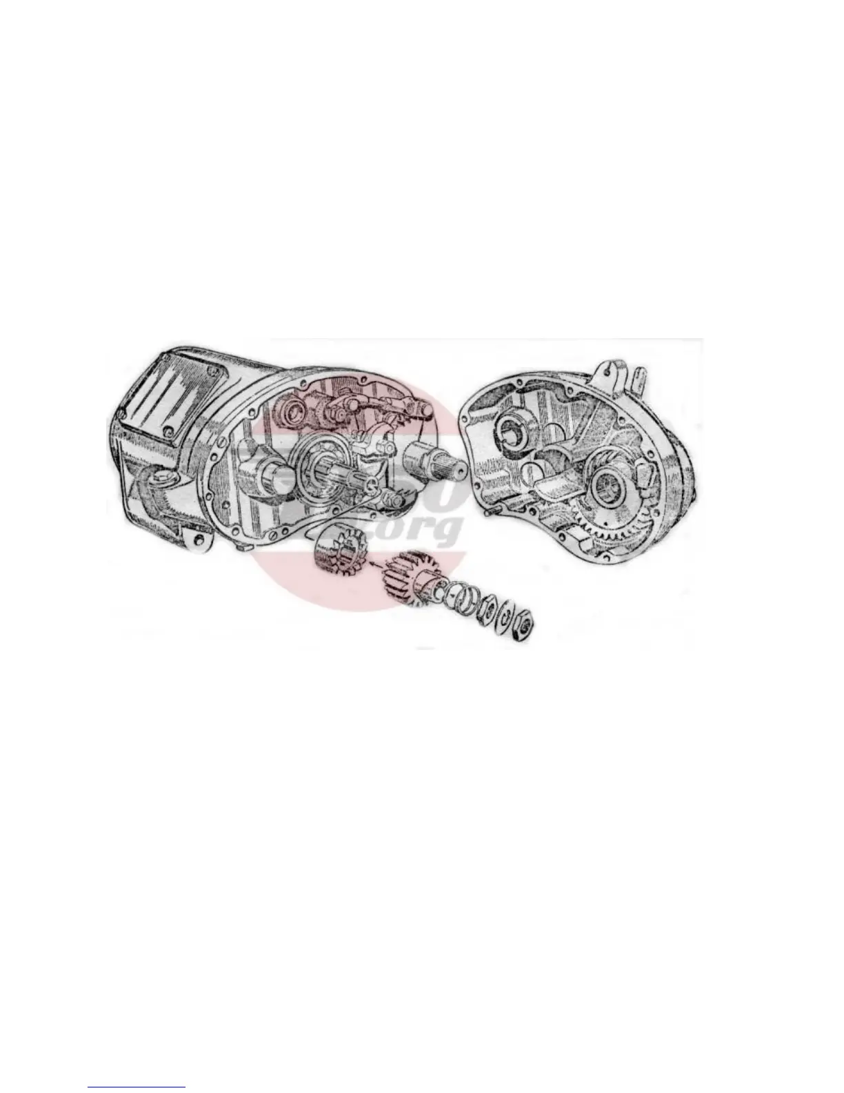
It is only possible to refit the shafts and their pinions
in the box provided that the shafts are first
assembled (with pinions in top gear position) outside
the gearbox and then all fitted together.
Commencing with the layshaft, take off the low gear
pinion only (this is the largest on the shaft) and hold
the shaft in the left hand with the drilled end towards
the wrist. Take up the selector shaft and fit the fork
nearest to the small pinion into the dog clutch on the
layshaft. Pick up the mainshaft, which should be
complete with its dog clutch, and put it in position so
that the second selector fork engages with the
mainshaft dog clutch. The whole assembly can now
be fitted into the gearbox, the mainshaft being the
first to enter its bearing. Verify again through the
inspection cover that the pinions are set in the top
gear position (see Fig. 35). In this position the dog
clutch on the mainshaft is in mesh with the pinion
sleeve.
Replace the low gear pinion on the layshaft and if all
has been assembled correctly, the face of this pinion
should
be just flush with its mating pinion on the
mainshaft. The oil flinger washer and spacing collar
can now be refitted to the mainshaft (see Fig. 35).
The inner cover is next to be assembled. Set the
selector quadrant in the top gear position (see Fig.
36) and replace the cover. The paper washer
between the inner cover and the gearbox shell
should be smeared with jointing compound before
final assembly. If the cover will not fit properly at the
first attempt, a slight
movement of the selector, by
means of a spanner, will cause the selector teeth to
mesh properly with the selector shaft pinion and then
the cover may be pressed home.
Replace the four screws and locking strip, bending
the corners of the latter to suit. All shafts should
have the minimum of end play, and engagement of
dogs should be checked in each gear.
The ratchet mechanism may now be refitted to the
mainshaft, the parts assembling in the following
order: Ratchet, bush, ratchet pinion, spring and
shouldered nut. The latter should be tightened by
finger pressure only. Replace the lockwasher and
note that the tongue in this washer engages with the
groove machined in the mainshaft. Screw up the
locknut very tightly, and tap the edge of the washer
over the nut.
RE-ASSEMBLY OF THE GEARCHANGE
The ratchet sleeve plate (i.e., the plate in which there
are a series of teeth) should be held in the left hand
with the shortest diameter of the sleeve uppermost
(see Fig. 38). One of the pawl carrier plates will be
seen to have thin washer welded on to both faces,
and this plate should now be superimposed upon the
ratchet plate so that the pawl fits into one of the teeth
adjacent to the link pin hole. Place the remaining
pawl carrier on top of the original one so that it’s pawl
engages with the second set of teeth on the ratchet
plate.
Still holding the gearchange assembly in the left
hand, take up the gearchange spindle in the right
hand, holding it by the threaded end and fit it into the
ratchet sleeve so that the plate fixed to the spindle
lies between the spring anchor pegs. With the aid of
a pair of pliers, replace the two springs and fit the
circlip in position. The whole process of re-assembly
of the gearchange mechanism will be made much
easier by a study of the illustration (Fig. 38).
The unit is now ready for re-assembly into the
gearbox. Make sure that the spring-loaded plunger is
in position behind the unit before it is replaced.
Couple the link arm to the ratchet plate and take care
to replace the split pin. It should not be necessary to
make any adjustment to the length of the link itself –
this has been set when the gearbox was originally
built, but if the gears will not engage properly a slight
adjustment to the length of the link will be sufficient.